


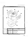


MODEL 8559A
OPERATION
spectrum analyzer is calibrated for absolute ampli-
tude and frequency measurements. Set the controls
as shown in Table 1 before you start the adjustment
procedure.
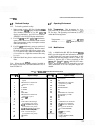
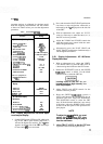
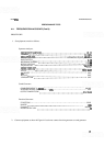
TABLE
1.
ADJUSTMENT SElllNGS
Function
Spectrum Analyzer Plug
-
In
INPUT ATTEN (dB)*
REFERENCE LEVEL
Option 002
REF LEVEL FINE
Amplitude Scale
FREQ
SPANIDIV
RESOLUTION BW
SWEEP
TIMEIDIV
SWEEP TRIGGER
START
-
CENTER
(8558B, 8557A)
FREQUENCY BAND GHz
(8559A)
TUNING
BASELINE CLIPPER
VIDEO FILTER
*On
older
plug
-
ins, set
OPTIMUM INPUT to
-
30
dBm.
-
-
HP 853A Spectrum Analyzer
Display
TRACE A
TRACE B
DGTL AVG
INPUT-B+ A
HP 180
-
Series Display
Mainframe
DISPLAY
MAGNIFIER
SCALE (1
80TR, l82T)
PERSISTENCE (1 8 1 T/TR)
Display Mode (1 81 TITR)
-
-
Setting
10 dB
0 dBm
+50 dBmV
0 dBm
LIN
10 MHz (uncoupled)
1 MHz (uncoupled)
AUTO
FREE RUN
CENTER
>60 MHz
OFF
OFF
WRITE
STORE BLANK
OFF
OFF
INT
X
1
OFF
MIN
WRITE
3
-
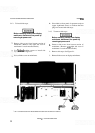
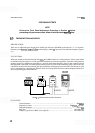
29. Display Adjustments
-
HP 853A Spec
-
trum Analyzer Display
1.
Switch LINE power OFF then ON while hold-
ing PLOT GRAT push button depressed to
activate the digital test routines. The
"#O" that
appears on the left side of the
CRT
means digi-
tal test routine
#O is now activated.
Press and release the PLOT GRAT push button
four times to step to digital test routine #4, as
indicated by the
"#4" displayed on the left side
of the CRT.
With an adjustment tool, adjust the FOCUS
control as necessary to make the characters on
the CRT as clear as possible.
Adjust the
X
POSN and Y POSN controls the
align the square trace pattern with the outer-
most CRT graticule lines.
Momentarily press the PLOT GRAT and
PLOT TRACE push buttons simultaneously to
exit the digital test routines.
3
-
30.
Display Adjustments
-
HP 180
-
Series
Display Mainframe
1.
With an adjustment tool, adjust the VERTI-
CAL POSN control to place the CRT trace on
a horizontal graticule line near the CRT center.
2.
Reduce the INTENSITY and set the SWEEP
TIME/DIV control to MAN. Use the MAN
SWEEP knob to center the CRT dot.
Leaving a dot on the CRT for pro
-
longed periods at high intensity can
burn the phosphor.
3.
Adjust FOCUS and ASTIG controls for the
smallest round dot possible.
4.
Reset the SWEEP
TIME/DIV control to
AUTO and increase the INTENSITY for an
optimum CRT trace. Adjust the HORIZON
-
TAL POSITION control to center the CRT
trace. If the horizontal deflection is not exactly
10 divisions, adjust the HORIZ GAIN control
located on the rear panel of the spectrum ana-
lyzer plug-in.
NOTE
To adjust the
HORIZ GAIN, you must
switch the
LINE power OFF, then
remove the spectrum analyzer plug
-
in
from the mainframe.
5.
Adjust TRACE ALIGN so that the CRT trace
is parallel to the horizontal graticule line.