


MODEL
8559A
TROUBLESHOOTING HINTS
Begin troubleshooting by measuring the mainframe
-
supplied voltages as close to the HP 8559A as possible. The
Vertical
Driver/Blanking Assembly A15 offers three test points (A15TP6, A15TP7, A15TP8) to make the
measurements. The
+
l00V supply is available at A15TP6, the
+
15V supply at A15TP7, and the
-
12.6V
supply at A15TP8. If any of these voltages are low, refer to the mainframe Operation and Service manual and
make the necessary adjustments before continuing. Common symptoms caused by low mainframe
-
supplied
voltages include: increased residual FM (caused by
a
low
+
15V supply) and poor frequency accuracy or inter
-
mittent lockup of the frequency display LED'S (also caused by a low power supply).
Residual
FM
Residual FM is a short
-
term jitter or an undesired frequency modulation of a local oscillator (LO). It appears as
noise riding on the displayed trace and may be random or cyclical (usually as a function of the line frequency).
The following procedure is a guide for isolating a source of residual FM. Further troubleshooting hints concern
-
ing residual FM are included following the circuit descriptions of the indicated assemblies.
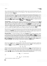
Set HP
8559A controls as follows:
FREQUENCY BAND
GHz
..................................................
.01- 3
...............................................................
TUNING .010GHz
FREQSPAN/DIV
...............................................................
0
RESOLUTION BW
.......................................................
300 kHz
INPUT
ATTEN
..............................................................
0 dB
REFERENCE
LEVEL
.....................................................
-
10 dB
REFLEVELFINE
..............................................................
0
Amplitude Scale
........................................................
10 dB/DIV
SWEEPTIME/DIV
........................................................
AUTO
SWEEPTRIGGER
...........................................................
OFF
.............................................................
VIDEOFILTER OFF
BLCLIP
....................................................................
OFF
.................................................................
SIGIDENT OFF
ALT IF
.....................................................................
OFF
Verify that the mainframe supply voltages are correct at the Vertical
Driver/Blanking Assembly A15 of the
HP
8559A by checking the voltages at A15TP6, A15TP7, and A15TP8.
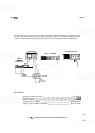
Use a second spectrum analyzer to check each LO of the HP 8559A for FM.
First LO: check at the HP
86559A front
-
panel RF input jack with test analyzer tuned to about
3
GHz
(LO power is
-
8 dBm
+
3 dBm).
Second LO:
check at
A5J3 on Second Converter Assembly AS.
Third LO: check at AlOJ1, the 300 MHz output on Third Converter Assembly A10.
If the source of FM is the first LO, check the Frequency Control Assembly A7 and the YIG
-
Tuned
Oscillator Assembly A6.
If the source of the FM is the second LO, short
A5A2TPl to ground while observing the second LO with
the second spectrum analyzer. This isolates the possible source of FM to the Second Converter Assembly
A5 by removing the varactor bias voltage. Note that removing this bias voltage will cause the second LO
frequency to shift. If FM is still present, check the Second Converter Assembly A5 as the source. If the FM
disappears, check the bias voltage source on the Marker Board Assembly A8.
If the source of the FM is the third LO, check the Third Converter Assembly
AlO.