


SERVICE
MODEL
8559A
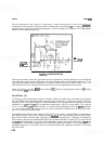
emitter is fixed by R8. The collector, therefore, becomes a constant
-
current sink for
20
rnA
of current supplied
by
Q1 and 43.
A
decrease in the current supplied by 43 results in increased current through Q1, keeping the
current through
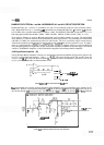
42 constant. If an LC filtered bandwidth is selected, BW5F (filtered bandwidth control line 5
in block C) supplies current via
CR1 and R13 (see Figure 8
-
47); 43 is effectively removed from the circuit.
0
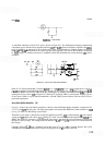
lOdB INPUT BUFFER AMPLIFIER
+15VF1
Rq
CB
FROM BW5F
IN BLOCK C
FIGURE
8
-
47.
DC
BIAS PATH DURING LC POLE OPERATION
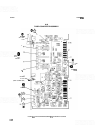
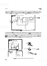
To understand how 43 functions during crystal filtering modes, a new model is needed. (See Figure 8
-
48.)
Resistor R7 has been omitted to simplify the model. The emitter load of
43
(RJ
is the series combination of the
internal resistance of
Y
1
(RJ
and a resistance determined by the bandwidth selected (see First Xtal Pole descrip
-
tion). The crystal's series resistance at resonance
(RJ
is constant at about 10 ohms. In the 30 kHz bandwidth,
R23* is in series with
k.
Since R23* is very large by comparison, it represents the total load on 43
(RJ.
When
R23* is substituted into the gain equation for
R,,
a gain of 2.7 (8.6 dB) results. This is roughly equal to the gain
without 43 in the circuit. In fact, the larger
R,
becomes, the closer the gains become.
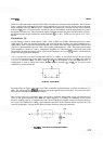
Q
lOdB INPUT
BUFFER AMPLIFIER
01
,02
R5
R6
I
T
-,
R3
FEEDBACK
I
4'
0
.
1-11
R5tR6
it
-
R3
OAIN
-
1-
-
At
FOR
30~
BW:
When: ~t-8250
n
185.7
110
Then: OAIN
-
23.7
-
2.89 OAIN 2.70
=
B.6dB
1
-
-
82.50
FOR
iK
BW:
When: Rt-70
a
Then: OAIN
-
2.8'
-
=
12dB
.€ia-'.O
FIGURE
8-48.
10
dB INPUT BUFFER AMPLIFIER DURING CRYSTAL FILTER OPERATION