


MODEL 8559A SERVICE
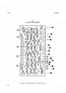
Sweep Ramp HighlLow Limit Comparator (C)
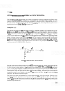
Operational amplifiers Ula and Ulb are connected to form a comparator circuit. A voltage divider, comprising
resistors R6, R7, and R8, establishes a high voltage reference at Ula pin
2
and a low voltage reference at Ulb
pin 5. The switching limits are approximately
+
5V and
+
0.7V, respectively. The signal applied to other inputs
of the comparator is the YIG tuning voltage, the same signal that drives the YIG main coil. It consists of the
analog tuning voltage and the sweep ramp
(S
+
T).
The tuning voltage is proportional to the instantaneous
frequency to which the analyzer is tuned; the ramp sweeps from
+
1.2V to 4.8V.
As the YIG tuning voltage at Ula pin
3
rises above the reference at Ula pin
2
(
+
4.95V), the output of Ula rises
to about
+
14V. This turns on 44 in the blanking driver and blanks the display. If the YIG tuning voltage goes
below the lower reference limit
(+0.7V), the output of Ulb goes to about
+
14V and again blanks the display.
The upper and lower blanking limits correspond to 50
MHz
below and 100
MHz
above the ends of each band
being swept.
VerticallBaseline Comparator (D)
The Vertical/Baseline Comparator consists of 416 and 48. The baseline clipping reference voltage is set by the
BL CLIP control
A2AlR2, which varies the base voltage of 416. The Vertical Preamplifier output signal is
applied to the base of
48 and compared to the dc reference voltage at the base of 416. If the signal becomes
more negative than the reference, Q8 turns on. This turns
44 on and blanks the display.
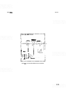
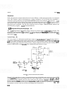
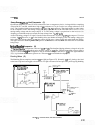
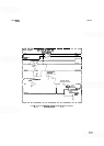
Blanking Driver
(F)
The Blanking Driver comprises transistors 44 and Q9 (see Figure 8
-
72). Normally, 44 is off, placing a low level
at the base of Q9 and causing Q9 to be turned on. For Q9 to be turned off and provide a positive going blanking
SWEEP RAMP
HI/LO LIMIT
COMPARATOR
i12 IN BYPASS
-
12 IN
MODE
CRT
BLANKING
MODE.
-11V TRACE
FIGURE
8-72,
BLANKING CIRCUIT, SIMPLIFIED SCHEMATIC