


ADJUSTMENTS
5
-
22. 3 dB BANDWIDTH ADJUSTMENTS (SERIAL PREFIX l9O9A) (Cont'd)
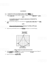
3. Set signal level of 7.1 divisions on display with REF LEVEL FINE control. (Signal should be 0.9 division
from top graticule line.)
4. Set RESOLUTION BW to
1
MHz
and FREQ SPAN/DIV to 200
kHz.
Adjust A9R85 LC to set band
-
width of 5 divisions at the fifth graticule line.
5.
Set RESOLUTION BW to 3
MHz
and FREQ SPAN/DIV to 500
kHz.
The bandwidth at the fifth grati-
cule line should be between 5.4 and
6.6
divisions.
NOTE
A9R85 LC may
be
further adjusted to bring the 3 MHz and
300
kHz band
-
widths within limits; however, the final measurement of the
1
MHz band.
width must
be
between 4.5 and 5.5 divisions at the fifth graticule line. (If the
3 MHz bandwidth cannot
be
brought within limits by adjustment of A9R85
LC,
change the value of factory-selected resistor A9R95*.)
6.
Set RESOLUTION BW to 300
kHz
and FREQ SPAN/DIV to 50
kHz.
The bandwidth should be between
5.4 and
6.6
divisions at the fifth graticule line. (If the bandwidth cannot be adjusted within the specified
limits, change the value of factory
-
selected resistor AgR89*
.)
7. Set RESOLUTION BW to 100
kHz
and FREQ SPAN/DIV to 20
kHz.
The bandwidth should be between
4.3 and 5.7 divisions at the fifth graticule line.
NOTE
If the
100 kHz bandwidth is not within the specified limits, change the
values of
factory-selected resistors A13R19*, A13R43*, and A11R43*. If the
bandwidth is too wide, increase the value of the resistors; if the bandwidth
is too narrow, decrease the value of the resistors. The three
factory-selected
resistors need not
be
of equal value, but each must
be
within one standard
value of the others.
8. Set RESOLUTION BW to 30
kHz
and FREQ SPAN/DIV to 10
kHz.
The bandwidth should be between
2.6
and 3.4 divisions at the fifth graticule line.
NOTE
If the 30 kHz bandwidth is not within the specified limits, change the values
of
factory-selected resistors A1
1
R23*, A1 1 R48*, A13R23*, and A13R48*. If
the bandwidth is too wide, decrease the value of the
factory-selected resis
-
tors; if the bandwidth is too narrow, increase the value of the resistors. The
four
factory-selected resistors need not
be
of equal value, but each must be
within one standard value of the others.
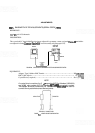
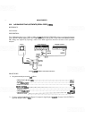
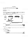
9. Connect signal generator through the BNC Tee connector to the step attenuator and to the frequency
counter
as
shown in Figure 5
-
8. Set the signal generator to approximately 0 dBm and the step attenuator to
30
dB.