


ADJUSTMENTS
MODEL
8559A
ADJUSTMENTS
5
-
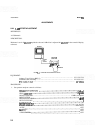
21. BANDWIDTH FILTER ADJUSTMENTS (Cont'd)
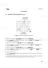
Adjust FINE TUNING and REF LEVEL FINE controls for a centered signal at
7
divisions from bottom
graticule line.
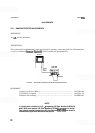
Remove shorts from
A13TP3 and A13TP6 and center signal with FINE TUNING control. Adjust
A13R26 LC for a signal amplitude of
7
divisions. Replace shorts on A13TP3 and A13TP6.
Remove shorts from A1 lTP3 and A1 1TP6. Adjust A1 1R26 LC for a signal amplitude of
7
divisions.
Repeat steps 36 through 40 until no further adjustment is necessary. Remove shorts from
AllTP3,
A1 lTP6, A13TP3, and A13TP6.
Adjust A1 1 R3 1 XTL and A1 3R3 1 XTL fully counterclockwise.
Set RESOLUTION BW to
1
kHz and FREQ SPAN/DIV to 10 kHz. Center signal with FINE TUNING
control. Adjust
A1 lR31 XTL and A13R31 XTL equally for a signal amplitude of
7
divisions. Each
potentiometer should be adjusted to accomplish half the necessary increase in signal amplitude.
Remove jumper from
A9TP6 and A9TP8.
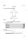
Set FREQ SPAN/DIV to 500 kHz and RESOLUTION BW to 3 MHz.
Center signal with TUNING control. Adjust REF LEVEL FINE control for a signal amplitude of
7
divisions.
Step down RESOLUTION BW from 3 MHz tp
300 kHz. Variation in signal amplitude should be less than
-t
0.4 dB.
Set FREQ
SPAN/DIV to 10 kHz, TIME/DIV to AUTO, and step down RESOLUTION BW from 100
kHz to 1 kHz. Variation of signal amplitude should be less than
-t
0.7 dB from the 7th division reference.
Repeat steps 35 through
46
until variation in signal amplitude is within limits.
NOTE
If amplitude variation between crystal and LC poles exceeds specification,
A1 1
R7*IA13R7* can be replaced to bring the crystal poles to the amplitude
of the LC poles.