


SERVICE
NOTE
MODEL
8559A
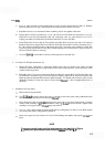
Rear Drive Hub (15) on Bandwidth Shaft (55) is preset flush with collar on
shaft (see Figure 8
-
7B). Do not remove drive hub unless necessary for repair.
e. Use a no. 4 hex wrench to loosen the two screws on Coupling Hub (54) attached to Frequency Span
Shaft
(9), and remove hub from shaft.
f. Remove the two Studs (53) used to support Bandwidth Switch Board (59). Remove Bandwidth
Detent (52) from Front Switch Assembly.
20. Remove the remaining Screws (48) attaching Front Switch Board Assembly
MA1 to Front Switch Diecast
(1).
21. Twist the left side of Front Switch Board Assembly MA1 down approximately l/&inch to provide clear
-
ance from Front Switch Diecast support arm (upper left corner). Lift Front Switch Board Assembly A2A1
from Front Switch Diecast (1) and set aside.
22. Removal of Rotor Assemblies:
a.
Remove Attenuator Drive Rotor
(8), front Anticrush Drive Hub Assembly (7), and Attenuator Shaft
Assembly (18) from Front Switch
Diecast
(I),
and set these parts aside.
b.
Remove Frequency Span Rotor (14) with associated parts (9
-
12, 15
-
17) from Front Switch Diecast
(I), and set aside. Be careful to keep Ball Bearings (10) and Springs (1 1) with Frequency Span Rotor
(14).
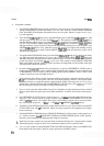
NOTE
Drive Hub (15) on Frequency Span Shaft (9) is preset at 12.954 mm (0.510 in.)
from end of shaft (see Figure 8
-
7C). Do not remove drive hub from shaft
unless necessary for repair.
c. Remove both remaining rotor assemblies from Front Switch Diecast (I), and set aside. Be careful to
keep Ball Bearings (10) and Springs (1 1) with their respective rotors.
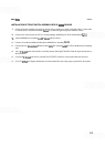
23. Disassembly of Lock:
a.
Press Locking Link
(5)
into Front Switch Diecast (I) to release pressure on Dowel Pin (4). Remove
Dowel Pin through cutout in Front Switch
Diecast. (Individual parts are identified in Figure 8-9.)
b.
Remove Locking Link
(9, Locking Shaft (3), and Lock Spring (2) from Front Switch Diecast.
CLEANING AND INSPECTION OF FRONT SWITCH ASSEMBLY
1.
All switch contacts must be totally clean and grease-free for proper operation. Use a 50-50 mixture of
isopropyl alcohol and distilled water to thoroughly clean switch rotor contacts and Front Switch Board
Assembly
A2A1. Avoid touching contacts with fingers.
2. Inspect for bent or damaged shafts, worn or broken contacts, weak or broken springs, rough feeling
potentiometers, cracked castings, and damaged PC boards. Check for signs of corrosion or rust. Replace
any suspect parts.
3.
A special Instrument Grease (HP Part Number 6040
-
0584) is recommended exclusively for use during
switch reassembly. Lubrication is essential for proper operation of switches and lock. A small brush is
recommended for applying the Instrument Grease.
8
-
28