


MODEL
8559A
ADJUSTMENTS
ADJUSTMENTS
5
-
19. LOG AMPLIFIER LOG AND LINEAR ADJUSTMENTS (Cont'd)
Linear Output and Linear Step Gain
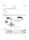
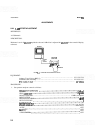
20. Disconnect AlOWl from step attenuator and reconnect to A5J2.
When reconnecting A1OW1 to A5J2, do not tighten to over
6
inch pounds of
torque;
A5J2 can be damaged if the connector is overtightened.
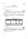
Set spectrum analyzer controls as follows:
INPUT
ATTEN
.............................................................
10 dB
REFERENCE LEVEL
....................................................
-
50 dBm
FREQ SPAN/DIV
...............................................................
0
.................................................................
TUNING 30MHz
Set signal generator controls as follows:
OUTPUT LEVEL
.................................................
approx.
-
5
dBm
............................................................
FREQUENCY 30MHz
Set 10
-
dB step attenuator to 0 dB.
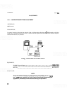
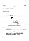
21.
Remove adapter from step attenuator and connect step attenuator to spectrum analyzer input. Adjust the
signal generator OUTPUT LEVEL for a DVM reading
(
k
1 mV) of 800 mV plus offset recorded in step 4
(measured at A
15TP I).
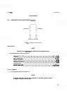
22.
Set spectrum analyzer amplitude scale for Linear display (LIN) and adjust LIN control
A14R34 for DVM
reading
(
k
1 mV) of 800 mV plus offset recorded in step 4.
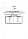
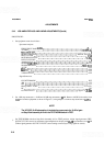
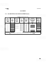
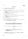
23. Make adjustments indicated in Table 5
-
8, then recheck that all steps meet the DVM test limits. Between
adjustments, recheck tuning of spectrum analyzer to be certain signal remains peaked.
TABLE
5-8.
LINEAR GAIN ADJUSTMENTS
Adjustment
*After subtracting offset.
A14R34
A14R33
A14R30
A14R27
No adjustment
Step Attenuator
0
10
20
30
40
Reference Level (dBm)
DVM
Reading
"
-
50
-
60
-
70
-
80
-
9
0
Ref: 800
+
1 mV
800 k5 mV
800 +5 mV
800 *5 mV
800 +20 mV