


MODEL 8559A
INSTALLATION AND OPERATION VERIFICATION
SECTION II
INSTALLATION AND OPERATION VERIFICATION
2-1.
INTRODUCTION
2
-
2.
This section includes information on initial
inspection, preparation for use, and storage and
shipping requirements for the HP
8559A.
2-3.
INITIAL INSPECTION
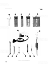
2-4. Inspect the shipping container for damage. If
the shipping container or cushioning material is dam
-
aged, it should be kept until the contents of the ship
-
ment have been checked for completeness and the
instrument has been checked mechanically and elec
-
trically. The contents of the shipment should be as
shown in Figure 1
-
1. The electrical performance is
checked by the Operation Verification procedure in
this section. If the contents are incomplete, or if the
instrument does not pass Operation Verification
tests, notify the nearest Hewlett
-
Packard office.
If
the shipping container is damaged, or the cushioning
material shows signs of stress, notify the carrier as
well as the Hewlett
-
Packard office. Keep the ship
-
ping materials for carrier's inspection. The HP office
will arrange for repair or replacement without wait
-
ing for claim settlement.
2
-
5.
PREPARATION FOR USE
2-6. Installation
2
-
7.
When properly installed, the spectrum ana
-
lyzer obtains all necessary power from the display
mainframe. The rear panel connector provides the
interface.
BEFORE SWITCHING ON THIS
INSTRUMENT, make sure it is
adapted to the voltage of the ac
power source to be used and the
proper fuse is installed. Failure to set
the ac power input of the instrument
for the correct voltage level could
cause damage to the instrument
when plugged in. Refer to the display
mainframe Operation and Service
Manual for line voltage and fuse
selection.
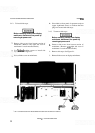
2
-
8.
To install the spectrum analyzer in the main
-
frame:
Set display mainframe
LINE
switch to OFF.
Pull out lock knob and slide plug
-
in toward rear
of compartment until it is seated firmly in
place.
Push in lock knob to secure spectrum analyzer
in mainframe.
Side Stop Kits
2
-
10.
Side stops unique to the installation of this
instrument into the HP 853A Spectrum Analyzer
Display are included with the HP
853A. Refer to the
HP
853A Operation and Service Manual for further
information.
2
-
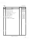
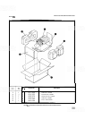
11. Installation of a Side Stop Kit, HP Part
Number
08558-60131, prevents the removal of the
analyzer from the HP 180
-
series mainframe without
the use of hand tools. This kit contains two side
stops, mounting hardware, label, and installation
instructions. (Refer to Table 2
-
1 for part numbers of
individual items.)
Quantity
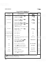
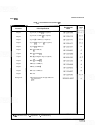
TABLE 2-1. SIDESTOP KIT (0855860131)
Description
Number
I
I
I
HPPart
SIDE STOP
MACHINE SCREW,
4
-
40,
,438
IN
-
LG
82
DEG FLATHEAD
LABEL, FRONT
-
PANEL
LABEL, INSTRUCTIONS