


ADJUSTMENTS MODEL 8559A
ADJUSTMENTS
5
-
21. BANDWIDTH FILTER ADJUSTMENTS
REFERENCE:
A9,
A1 1, and A13 Schematics
DESCRIPTION:
The crystal and LC bandwidth filter circuits are adjusted for symmetry, center, and peak. The 3
-
dB bandwidths
are adjusted with Sweep
Generator/Bandwidth Control Assembly A9 (paragraph 5
-
22).
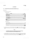
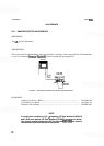
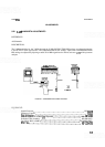
DISPLAY
SPECTRUM
ANALYZER
EXTENDER
CABLE
ASSEMBLY
0..
o...
l
NPUT
OUTPUT
ADAPTER
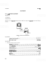
FIGURE 5
-
5. CRYSTAL AND LC BANDWIDTH FILTER ADJUSTMENTSTESTSETUP
EQUIPMENT:
.........................................
Adapter, Type N (m) to BNC
(f)
HP 1250
-
0780
..............................................
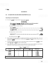
Crystal Short (3 required)
See Figure 5
-
6
..............................................
Extender Cable Assembly HP 5060
-
0303
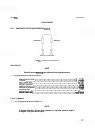
NOTE
A
crystal short consists of a .O1 pF capacitor (HP Part Number 0160
-
0161)
and a 90.9 ohm resistor (HP Part Number 0757
-
0400) connected in series.
Two square terminal connectors (HP Part Number
0362-0265) are used to
connect the crystal short across the test points.