


SERVICE
MODEL
8559A
k.
Pull and turn FREQ
SPAN/DIV Knob until a set screw is visible on Coupling Hub
(54).
Push FREQ
SPAN/DIV knob in and out to align pin on Coupling Hub with slots in Bandwidth Rotor (56). With
FREQ
SPAN/DIV knob pushed in and Coupling Hub flush again Bandwidth Rotor (pin aligned),
tighten set screw using a no. 4 hex wrench. Turn FREQ
SPAN/DIV knob until second set screw is
visible, and tighten second set screw.
1. Push FREQ
SPAN/DIV knob in and out while observing Bandwidth Rotor (56). Bandwidth Rotor
will not move if Coupling Hub (54) is properly aligned. Readjust Coupling Hub as necessary for
proper operation.
5.
Assembly of REFERENCE LEVEL Switch:
a. Install remaining two Studs (53) on Front Switch Assembly. Check that all screws and studs have
been tightened.
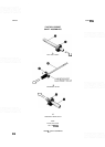
b. If rear Anticrush Drive Hub Assembly (7) has been loosened or removed from Ref Level Shaft
(6),
refer to Figure 8-7A for correct dimensions for adjustment.
c.
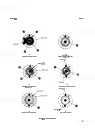
Inspect Ref Level Rotor (60). Roll Pins (12) should be positioned in hole 1 and hole
9,
as shown in
Figure
8-8E Check that Spring (1 1) and Ball Bearing (10) are in position. Insert Ref Level Shaft (6)
through Ref Level Rotor so that rear Anticrush Drive Hub (7) seats properly into rotor.
d.
Lightly grease long end of Ref Level Shaft (6) and insert through Front Switch Board Assembly
A2A1, Attenuator Drive Rotor (8), front Anticrush Drive Hub (7), and bushing in Front Switch
Diecast (1).
\
e. Lightly grease detent holes on flat side of Ref Level Detent (61). Mount detent on three Studs (53)
and fasten tightly with three Standoffs (62).
Hollow Ref Level Shaft (6) might be damaged
if
set screws in Rotating Lock
-
out (63) are tightened excessively.
f. Place Rotating Lockout (63) on Ref Level Shaft (6) with teeth flat against Ref Level Detent (61).
Lockout teeth should be aligned to miss pin on Ref Level Detent when Ref Level Shaft is pushed in
(switch in any detent position). With Ref Level Shaft fully extended from front panel, use a no. 4 hex
wrench to tighten Rotating Lockout.
g.
Push Ref Level Shaft (6) in and out and check for smooth mechanical feel and proper Rotating
Lockout (63) alignment. Rotating Lockout should not bind against Ref Level Detent (61) and should
allow Ref Level Shaft to turn smoothly between detent positions. Adjust Rotating Lockout as neces-
sary for proper operation.
h. Use a no. 4 hex wrench to lightly tighten one set screw in front Anticrush Drive Hub (7) visible
between Attenuator Drive Rotor (8) and Front Switch
Diecast (1).
i. Turn Attenuator Drive Rotor (8) so that long pin (for input Attenuator pointer) is at bottom of Front
Switch
Diecast
(1).
Hold Attenuator Drive Rotor in position and push in on Ref Level Shaft (6) to
align front Anticrush Drive Hub (7).
j.
Push Ref Level Shaft (6) in and out while observing Ref Level Rotor (60) and Attenuator Drive Rotor
(8). Rotors will not move when front Anticrush Drive Hub (7) is properly adjusted.