


ADJUSTMENTS
5
-
19.
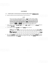
LOG AMPLIFIER LOG AND LINEAR ADJUSTMENT (SERIAL PREFIX 22O8A)
(Cont'd)
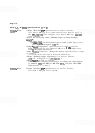
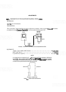
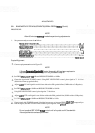
Connect equipment
as
shown in Figure 5-3. Set signal generator frequency to 321.4
MHz
and output level
to
-
40
dBm. Remove AlOW 1 from A5 J2 2nd CONV OUT. Connect signal generator output through step
attenuator and adapters to
AlOWl
.
Set the TEST-NORM switch A12S1 to the TEST position. The signal generator frequency for maximum
signal amplitude on oscilloscope display with step attenuator set at
0 dB.
Set output level of signal generator for a digital voltmeter reading of 700
mV, with step attenuator set at 0
dB and REF LEVEL dBm set to
-
50.
Set
HP
8559A REF LEVEL dBm to
-
80
and set step attenuator to 30 dB. Observe digital voltmeter
reading.
Adjust
A14R3 GAIN LIN for a digital voltmeter reading of
700
mV.
Repeat steps 4,5, and
6
until the DVM reading
in
step 5 is 700
+
2 mV.
Set
HP
8559A REF LEVEL dBm to
-
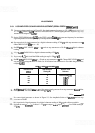
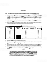
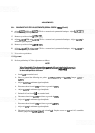
50 and set step attenuator to 0 dB. Change REF LEVEL dBm and
step attenuator settings
as
shown in Table 5-6. If Deviation from Reference is not within the given limits,
readjust
Al4R3.
TABLE
5-6.
LINEAR GAIN ADJUSTMENT LIMITS
Reference Level
I
hJB4
Set
HP
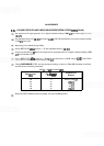
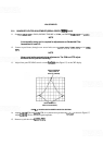
8559A REF LEVEL dBm to
0
and disconnect signal generator from step attenuator. Record offset
reading (DVM). The offset should be less than
+
30 mY
-
50
-
60
-
70
-
80
-
90
d
Offset mV
Step Attenuator
Setting (dB)
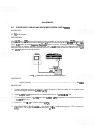
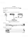
Reconnect signal generator
as
shown in Figure 5
-
3. Set Amplitude Scale to 10 dB/DIV and set step
attenuator to
40
dB.
Deviation From
Reference
0
10
20
30
40
Set
output level of signal generator for a digital voltmeter reading of
400
mV
plus offset recorded in
step
Reference
(700 mV)
*lo
mV
k20 mV
k20
mV
k30 mV
9 (al
g
ebraic sum). (Example: if offset if
-
23 mV, set output levelof signal generator for a DVM reading of
377
my)