


Pages 8
-
67 through 8
-
81/8
-
82:
FBEQOEWCY
COIlTROL
ASSEHBLY
A7
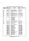
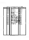
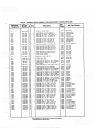
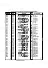
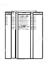
Table 8-4. Frequency Control Assembly A7, Replaceable Parts
2236A
&
Below
Replace Table 8
-
4 with new Table 8
-
4 (SERIAL PREFIX 2236A)
included in this Manual Backdating supplement.
2208A
&
Below
Make the
following changes to new Table 8
-
4 (SERIAL PREFIX
22368
:
Change A7 to HP Part Number 08559
-
60021, Check Digit 7.
Add
A7C1 and A7C2, HP Part Number 0180-2208, Check Digit 6,
CAPACITOR
-
FXD 220UF +-lo% lOVDC TA.
Add A7Cl1, HP Part Number 0160
-
2055, Check Digit 9, CAPACITOR
-
FXD
.
O1UF +80-20% 100VDC CER.
Delete the following:
A7C13, A7C14, A7CR8, A7CR9, A7Q19, and A7Q20.
Change A7R30 to HP Part Number 0698-3428, Check Digit 1,
RESISTOR 14.7 1%
.125W F TC=O+-100.
Change A7R31 to HP Part Number 0757-0199, Check Digit 3,
RESISTOR
21.5K 1% .125W F TC=O+-100.
Add A7R98, HP Part Number 0757-0465, Check Digit 6, RESISTOR
lOOK 1% .125W F TC=O+-100.
Delete the following:
A7R100, A7R101, A7R102, A7U12, and A7VR1.
Add A7W1, HP Part Number 8159-0005, Check Digit 0,
WIRE
22AWG
W
PVC 1x22 80C.
2004A
&
Below Delete A7R99.
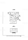
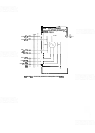
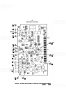
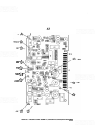
Figure 8
-
28. Frequency Control Asserbly A7, Component Locations
2236A
&
Below
Replace Figure 8
-
28 with new Figure 8
-
28 (SERIAL PREFIX 2236A)
included in this Manual Backdating supplement.
2208A
&
Below
Replace Figure 8
-
28 with new Figure 8
-
28 (SERIAL PREFIX 2208A)
included in this Manual Backdating supplement.
Add the following to Figure 8
-
28 (SERIAL PREFIX 2208A):
Add C12 between TP2 and the negative
(-1
side of
C8.
Add R99 to the left of TP7.
2004A
&
Below Delete A7R99.
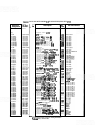
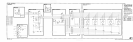
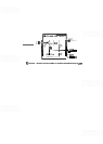
Figure
8
-
29.
Frequency Control Assembly
67,
Schematic Diagram
(1
of
2)
22361
&
Below Replace Figure 8
-
29 (1 of 2) with
new
Figure 8
-
29
(1
of 2)
(SERIAL PREFIX 2236A) included in this Manual Backdating
supplement.
2208A
&
Below Make the following changes to Figure 8
-
29 (1 of 2) (SERIAL PREFIX
22368)
:
Change A7 to HP Part Number 08559
-
60021.
In function block
(A), add R98, 100K, as follows:
Open the
FM/MAIN
lice at the left side of
R33.
Connect one side of R98
to
the left
side
of
R33.
Connect the other side of R98 to the FM/MAIN line.