


MODEL 8559A SERVICE
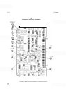
MARKER ASSEMBLY A8, CIRCUIT DESCRIPTION
The Marker Assembly A8 comprises the Marker Generator, the DPM and Second LO Drivers, the ALT IF and
SIG IDENT circuits, the Auto Scan Time Drivers, and the Scan Attenuators.
Marker Generator
(F)
The Marker Generator is basically a zero voltage detector. The four summed resistor voltages at pin 5 of U14
equal OV only when the sweep voltage and the tune voltage correspond to the same frequency. The marker is
then displayed at that frequency. If the input of
U14b (pin
5)
is at
OV,
the outputs (pins 7 and 1) should be at
OV.
The anodes of CR7 and CRlO should therefore be at OV also. Resistor R45 pulls their cathodes down to about
-0.N This turns on U6c, which normally has its emitter held to about +0.7V
(+
1.2V in fullband). As the
emitter voltage of
U6c increases, it turns on Q1. This pulls the video shift line down, shifting the signal and
noise at the Log Amplifier Assembly A14 about one division toward the bottom of the screen. The output of
the Log Amplifier Assembly A14 is permitted to be pulled low by the log shift resistor
(A14R119) at its output.
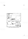
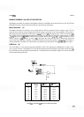
DPM Driver (D)
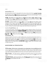
The DPM Driver is an inverting operational amplifier circuit. The appropriate combination of input, offset,
and feedback resistors is selected by U5 for the chosen frequency band (see Figure 8
-
30). Input control lines H2,
H3, and PM carry the encoded band information. A truth table on the schematic, Figure 8
-
33, shows the levels
of these lines during each band.
t
R
offset
R
Feedback
SELECTS
R
~nput
R
offset
R
Input and
R
Feedback
Band
R
Offset
R
Feedback
FIGURE
8-30,
DPM DRIVER GAIN SELECTION. SIMPLIFIED DIAGRAM