


ADJUSTMENTS
5
-
21.
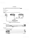
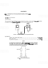
BANDWIDTH FILTER ADJUSTMENTS (SERIAL PREFIX 1909A) (Cont'd)
16. Adjust A13C15
SYM
and A13C25 CTR for a centered and symmetrical bandpass. Adjust A13C25
CTR
for minimum signal amplitude,
17.
Remove crystal short from
A1 lTP4/TPS..
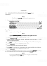
18. Adjust A11C38
SYM
and AllC54 CTR for a centered and symmetrical bandpass. Adjust AllC54 for
minimum signal amplitude.
19.
Remove crystal short from
A1 1TP 1/TP2.
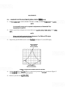
20. Adjust AllC15
SYM
and AllC25 CTR for a centered and symmetrical bandpass. Adjust AllC25 for
minimum signal amplitude.
21. Remove the crystal shorts.
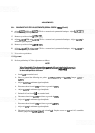
LC
Alignment
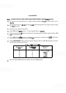
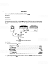
22. Perform preliminary LC filter adjustments as follows:
NOTE
When Bandwidth Filter Assemblies
A1 1 and A13 are installed with covers in
place, midget copper alligator clips (HP Part Number
1400-0483) can be
used
to short test points to the cover.
a. Install A13 on extender board.
b.
Short to ground the following test points: A13TP6, AllTP3, and AllTP6. Jumper A9TPl to
A9TP2.
c. Adjust A13C73 lor minimum signal amplitude.
d. Disconnect short from A1
3TP6 and short to ground A1 3TP3.
e. Adjust A13C74 for minimum signal amplitude.
f.
Reinstall A13 and install
A1 1 on extender board.
g. Disconnect short from
A13TP3 and short to ground A1 1TP6.
h. Adjust A1 1C73 for minimum signal amplitude.
i.
Disconnect short from A1 1TP6 and short to ground A1 1TP3.
j. Adjust A1 1C74 for minimum signal amplitude.
k.
Disconnect shorts from test points and reinstall A1 1. Replace covers on A1
1
and A13 assemblies.
Remove jumper from
A9TP 1 /A9TP2.