


ADJUSTMENTS
5
-
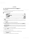
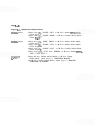
25. FIRST CONVERTER ADJUSTMENTS (SERIAL PREFIX 2236A) (Cont'd)
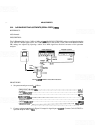
Connect frequency counter to analyzer
RF
Input.
Jumper
A16TP1 DIODE BIAS to Ground. A16TP1 is located on the Motherboard through a hole in the
analyzer side frame.
Adjust front-panel TUNING control for DVM indication of
0.000 Vdc (fully counterclockwise).
Adjust
A7R74 3 GHz for frequency counter indication of 3.000 GHz
+
1 MHz. If this adjustment cannot
be achieved, selectable resistor
A7R94* can be changed to provide the proper range necessary.
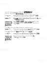
Adjust front-panel TUNING control for DVM indication of
-
10.000 Vdc.
Set
A7R95 6 GHz F (fine) to approximately midrange (R95 is a 20-turn potentiometer).
Adjust
A8R28 6 GHz C (coarse) for a frequency counter indication of 6.000 GHz
*
2 MHz.
Retune front-panel TUNING control for
0.000 Vdc DVM indication and readjust A7R74 3 GHz if neces-
sary for frequency counter indication of
3.000
GHz
+
1 MHz.
The front-panel TUNING control for
-
10.000 Vdc DVM indication.
Lightly tap the top edge of the A7 Frequency Control board with the handle of a small screwdriver to seat
controls.
Adjust A7R95 6 GHz F (fine) for frequency counter indication of 6.000 GHz
+
1
MHz.
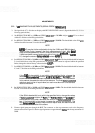
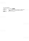
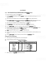
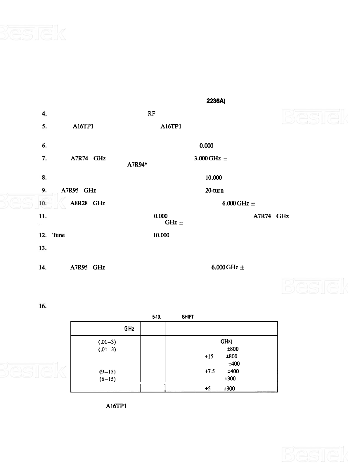
Alternate IF First LO Shift Check
15.
Press front-panel ALT IF pushbutton IN to activate alternate IE
Verify YTO frequency shift according to the following table.
I
6
(12.1
-
21)
I
ON
I
Reference
t5
MHz
k300
kHz
TABLE
5-10.
FIRST
LO
SHIFT
CHECK
17. Remove jumper from A16TP1 DIODE BIAS to Ground.
FREQUENCY BAND
GHz
1
(.Ol-3)
1
(-01-3)
2
(6
-
9)
3
(3
-
9)
4
(9-15)
5
(6-15)
ALT IF
OFF
ON
ON
ON
ON
ON
FREQUENCY COUNTER INDICATION
Reference
(6.000
GHz)
Reference
-
1
5
MHz
+800
kHz
Reference
t15
MHz
+800
kHz
Reference
-
7.5
MHz
k400
kHz
Reference
t7.5
MHz
*400
kHz
Reference
-
5
MHz
+300
kHz