


MODEL
8559A
SERVICE
i.
Use a no. 4 hex wrench to temporarily install SWEEP TRIGGER, SWEEP TIME/DIV, MANUAL
SWEEP, and FREQ
SPAN/DIV knobs.
j.
Tighten Stud (53) and left-most Screw (48) attaching Front Switch Board Assembly to Front Switch
Diecast (1). Check all switch rotors for smooth, free switch action. Readjust position of Front Switch
Board Assembly as necessary for proper switch action.
k. Tighten the two remaining Screws (48) attaching Front Switch Board Assembly to Front Switch
Diecast (1).
1. Recheck all switch rotors for smooth, free switch action and readjust Front Switch Assembly as
necessary.
4. Assembly of RESOLUTION BW switch:
a. Place Coupler Hub (54) on Frequency Span Shaft (9) with pin facing up (away from Front Switch
Assembly). Do not tighten Coupler Hub at this time.
b.
Center Bandwidth Detent (52) over Coupler Hub (54) with stop tab towards top of Front Switch
Assembly, and fasten to Front Switch Assembly using two Studs (53).
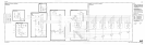
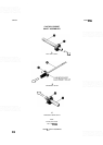
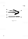
c. If Drive Hub (15) has been removed or loosened from Bandwidth Shaft (55), refer to Figure 8-7B for
proper adjustment. Lightly grease narrow end of Bandwidth Shaft (55) and detent holes on Band-
width Detent (52). Insert Bandwidth Shaft (55) through Frequency Span Shaft (9).
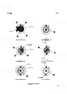
d. Inspect RESOLUTION BW Rotor (56). Roll Pins (12) should be positioned in hole 16 and hole
17
as
shown in Figure
8-8E. Check that Springs (23) and Ball Bearings (10) are in position.
e. Place RESOLUTION BW Rotor (56) onto Bandwidth Shaft (55). Position RESOLUTION BW
Rotor assembly so that stop tab does not fall within small span between Roll Pins (12).
f.
Clean contact fingers on RESOLUTION BW Rotor and switch traces on Bandwidth Switch Board
(59) using lint-free cloth and isopropyl
alcohol/distilled water mixture.
g.
Use a
1/4-inch nut driver to fasten Bandwidth Switch Board (59) to Front Switch Assembly with two
Hex Nuts (20). End of Bandwidth Shaft (55) must not bind against hole in board. Align MANUAL
SWEEP Shaft (22) with MANUAL SWEEP Potentiometer (58) by turning MANUAL SWEEP
knob clockwise until shaft engages with MANUAL SWEEP Potentiometer.
NOTE
Depth of MANUAL SWEEP Shaft
(22)
can be adjusted
if
necessary by care
-
fully tapping SWEEP TlMElDlV Shaft
(24)
farther into the white plastic rotor.
h.
Turn Front Switch Assembly over and remove FREQ
SPAN/DIV knob using a no. 4 hex wrench.
i.
Install Retainer Clip (21) on Bandwidth Shaft (55).
j.
Use a no. 6 hex wrench and a no.4 hex wrench to temporarily install FREQ SPAWDIV and RESO
-
LUTION
BW
knobs.
831