


MODEL 8559A ADJUSTMENTS
ADJUSTMENTS
5
-
28. FREQUENCY RESPONSE ADJUSTMENTS (Cont'd)
57. Change spectrum analyzer Amplitude Scale to 1 dB/DIV.
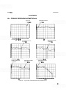
58. Adjust A12R71 V3
-
(bias), A12R61 5A (offset), A12R53 5B (tilt), and A12R54 5C (breakpoint) for best
overall flatness of trace from 6 to 15
GHz with trace approximately centered about the sixth horizontal
graticule line on the CRT.
59. Total deviation of trace from 6 to 15
GHz should not exceed 4.2 dB.
12.1 to 21 GHz Adjustment
NOTE
If an HP
862908-H08 (2
-
22 GHz plug
-
in) is not available, a standard HP
86290B (2
-
18.6 GHz plug
-
in) may be used to adjust the spectrum analyzer
flatness from 12.1 to 18.6
GHz using this procedure.
Change synchronizer POLARITY to
+
.
Change spectrum analyzer Amplitude Scale to 10 dB/DIV and FREQUENCY SPAN GHz to 12.1
-
21.
Adjust sweep oscillator for swept output from 12 to 18.6
GHz or 12 to 21 GHz, depending on which RF
plug
-
in is used.
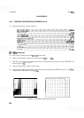
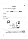
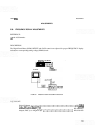
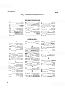
Adjust Tuning Voltage Circuit GAIN and OFFSET controls to phase-lock swept signal from 12 to 18.6
GHz or 12 to 21 GHz. Refer to Figure 5
-
19f.
Change spectrum analyzer Amplitude Scale to 1
dB/DIV.
Adjust A12R70 V3
+
(bias), A12R62 6A (offset), A12R55 6B (tilt), and A12R56 6C (breakpoint) for best
overall flatness of trace from 12.1 to 18.6
GHz or 12.1 to 21 GHz with trace approximately centered about
the sixth horizontal graticule line on the CRT.
Total deviation of trace from 12.1 to 18
GHz should not exceed 4.6 dB and from 18 to 21 GHz should not
exceed 6.0 dB.
If unable to achieve flatness specifications, it may be necessary to plot a characterization curve of the
sweep oscillator output from 12 to 21
GHz. This can be done by measuring the power output of the sweep
oscillator (at the 20 dB attenuator) every
500 MHz from 12 to 21 GHz using a power meter. The values
obtained can then be plotted on the CRT and flatness adjusted to this corrected curve. Total deviation then
becomes the difference between the largest positive and largest negative deviation from the plotted curve.
This characterization will require the use of an 18
-
21 GHz thermistor mount and K
-
Band waveguide
adapter in addition to equipment previously used. Recommended equipment is listed under EQUIPMENT
in this procedure along with previously used equipment.