


SERVICE
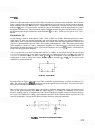
Second Xtal Pole
(G)
The operation of the Second Xtal Pole is identical with the First Xtal Pole.
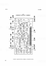
MODEL
8559A
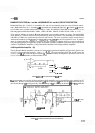
Second LC Pole
(F)
Operation of the Second LC Pole is the same
as
the First LC Pole, except that R56* performs the same function
as PIN diode
CR5.
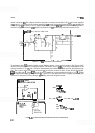
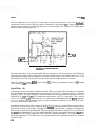
Output Buffer Amplifier (H)
The Output Buffer Amplifier is
a
complementary pair of transistors in which Q9 acts
as
a source follower with
its output current boosted by
Q10. The current through input FET Q9 is established by R53:
I,,,
=
Vb,(Q10)/R53
Which becomes:
I,,,
=
.7/196 or about 3
mA.
The total current through Q9 and Q10 is set by R54. The input signal path is selected by either CR15 (during
crystal mode) or CR16 (during LC mode).
BANDWIDTH FILTERS No. 1 and No.
2
ASSEMBLIES A1
1
and A1
3,
TROUBLESHOOTING
Observe front panel switch positions in relation to the problem to isolate the area of the failure.
Check for leaky diodes and capacitors. Loading of the signal path can alter either a pole's gain or
bandpass
shape or both.
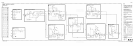
Isolate crystal poles from LC poles to prevent interaction of failure symptoms. Isolation of the crystal poles
from the circuit is best achieved by removing CR8 and
CRl5 (blocks
D
and
G).
Isolation of the LC poles is best
achieved by removing CR9 and CR16 (blocks C and F).