


SERVICE
MODEL
8559A
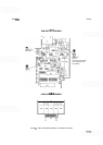
FRONT SWITCH ASSEMBLY A2 DISASSEMBLY AND REPAIR
REMOVAL OF FRONT SWITCH ASSEMBLY FROM HP
8559A CHASSIS
Turn HP 8559A upside down on a flat work surface.
NOTE
Numbers in parentheses match the numerical
callouts on Figure 8
-
10 Front
Switch Assembly (exploded view). All illustrations referenced in these pro
-
cedures follow the last procedural step.
Use a 9/16-inch nut driver (drilled out, if necessary, to fit over front panel BNC connectors, and covered
with heatshrink tubing or tape to avoid scratching enameled front panel) to remove dress nut holding CAL
OUTPUT connector to front panel.
Remove bottom guide rail. Use a
5/16-inch open
-
end wrench to carefully disconnect semi
-
rigid CabIe W2
from Input Attenuator Assembly A3 to First Mixer Assembly A4.
Disconnect two
40-conductor Ribbon Cables, A2AlWl (46) and A2AlW2 (47) from Motherboard
Assembly A16.
Turn HP
8559A right
-
side up, with front panel facing you.
Remove screw holding cable clamp to Second Converter Filter Assembly
A5A2. Remove screw located
below cable clamp that was removed.
Remove the four screws attaching Front Switch
Diecast (1) to left and right side gussets. Remove Front
Switch Assembly
A2, with Front Panel and RF Input Attenuator Assembly A3, from HP 8559A chassis
and set chassis to one side.
DISASSEMBLY OF FRONT SWITCH ASSEMBLY
Remove the following front panel knobs: FINE TUNE, COARSE TUNE, RESOLUTION BW, FREQ
SPAN/DIV, REF LEVEL FINE, and REFERENCE LEVEL (including Index Disc, Retaining Cup,
Nylon Spacer
Washer(s), Conical Spring, and Input Attenuator pointer).
Remove SWEEP TRIGGER, MANUAL SWEEP, and SWEEP
TIME/DIV knobs using a no. 4 hex
wrench.
Use a no. 4 hex wrench to loosen the two set screws in Lock Knob. Remove Lock Knob.
Remove VIDEO FILTER and BASELINE CLIPPER knobs using a no. 2 spline (Bristol) wrench.
Remove retaining ring on coarse tune shaft. Remove the three flat washers and two wavy washers.
Remove front panel hex nut and lockwasher on Coarse Tune Bushing (36) using a
1/2-inch nut driver
(covered with heatshrink tubing or tape to avoid scratching enameled front panel).
Loosen hex nut attaching
RF
Input Cable Assembly W1 to Front Switch Assembly
A2
using a 5/8-inch
open
-
end wrench. Carefully disconnect input cable assembly from RF Input Attenuator Assembly A3
using a
5/16-inch open
-
end wrench. Remove input cable assembly from Front Switch Assembly A2.