


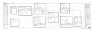
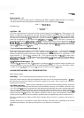

MODEL 8559A
SERVICE
/
SECOND
STAGE
\
i1iV
i1lV
-1OdB
ADJUST
A-
-
C
FEEDBACK
PITH
1,
.
LOG/LIN
L
I
N
E
-BVT
.Jk-@$
Q24
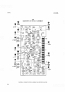
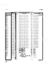
FIGURE
&66.10dB
GAIN OPERATION
IN
LINEAR MODE, SIMPLIFIED SCHEMATIC
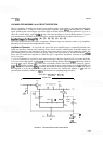
collector of 424 goes to
-
8
VT, turning the log diodes on. In Lin mode, the LOG/LIN line is at
-
8
VT, 424 is
turned off and current flows through R34 (LIN) to stages 6 and 7.
Log Mode Temperature
-
Controlled Variable
-
Gain Amplifier
(J)
In Lin mode, when approximately 700 mV rms
(+
10 dBm) is applied to the input of the Log amplifier, the
voltage at the output of stage 7
(TP5) is about 1.5 rms. With the same input in Log mode, the output at TP5 is
about
2.OV rms. To maintain an equal relationship with maximum input signal (the trace at top display), the
output in Log mode must be attenuated. This attenuation is achieved with variable gain amplifier 47, the gain
of which is determined by the ratio of its collector load to its emitter load.
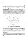
In Lin mode, the LOG/LIN line is a
-
8
VT, CR4 is forward biased, and the output of U2b (TP1) is approxi
-
mately
+
151 Diode CR29 is reverse biased and the gain of the variable gain amplifier is R104/R105 (100/316)
or approximately 0.3. In Log mode, the LOG/LIN line is at
+
15V, CR4 is reverse biased, and the output of
U2b
(TPI) is about -0.45V. Diode CR29 is forward biased and exhibits an ac resistance of about 100 ohms.
This resistance is in parallel with the 100 ohms of
R104 for a total of 50 ohms. Since the collector load of 47 is
about 50 ohms, the gain becomes 0.15
(50/316). This gain depends upon the resistance of CR29, which is
established by SLOPE adjustment
R23.
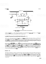
Detector
(K)
The detector comprises a voltage
-
to
-
current converter, a half
-
wave rectifier, and a low
-
pass filter. The output of
the variable gain amplifier is applied to 46, where voltage variations are converted to current variations.
Transistor Q5 acts as a current driver for half
-
wave rectifier 44, while CRl biases 44 just below cutoff. When
the signal is positive going,
44 conducts; during the negative half
-
cycle, Q4 is cutoff. The detector's output goes
to the low
-
pass filter,
a
series of pi
-
section filters that smooth the detector's output and remove
RF
signal
components.