


OPERATION
MODEL
8559A
3
-
17.
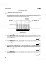
The frequency group enables the operator to
control how the Spectrum Analyzer displays the fre-
quency domain. The RESOLUTION BW and FREQ
SPAN/DIV controls, when pushed in, are coupled
together, and moving either control moves the other.
When the SWEEP
TIME/DIV control is in the
AUTO position, varying the RESOLUTION BW or
the FREQ
SPAN/DIV (coupled or uncoupled) will
change the sweep time to maintain calibration. With
the two controls coupled together in the optimum
position, RESOLUTION
BW's of 3 MHz to 1 kHz
will be automatically selected as the FREQ SPAN/
DIV is narrowed from F (Full) to
0 (Zero). TUNING
controls coarse and fine (coarse is larger knob) set
the center frequency of the displayed spectrum. RES
-
OLUTION BW control determines the resolution of
the signals on the CRT.
3
-
18. Amplitude.
The amplitude group consists
of:
REFERENCE LEVEL
dBm
INPUT ATTEN
REF LEVEL FINE
REF LEVEL CAL
10
dB/DIV
-
1 dB/DIV
-
LIN (Amplitude Scale)
3-19. The amplitude group enables the operator to
measure signal amplitude in units of either voltage or
dBm.
3
-
20. OPERATING PRECAUTIONS
3
-
21. Signal lnput
3-22. The
HP
8559A Spectrum Analyzer plug-in is
a sensitive measuring instrument. Overloading the
input with too much power, peak voltage, or dc volt-
age will
permaner:tly damage the input circuits. Do
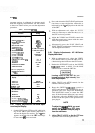
not exceed the input levels specified below:
Maximum lnput (Damage) Levels
HP
8559A
Total Power:
+
20 dBm (0.1 W, 2.2 Vrms) with 0 dB input
attenuation
+
30 dBm (1 W, 7.1 Vrms) with
1
10 dB input
attenuation
dcorac(<100
Hz):
k7.1V
Peak Pulse Power:
+
50
dBm (100W, >lOpsec
pulse width, 0.01% duty cycle) with
L
30 dB input
attenuation
NOTE
When you are measuring input sig
-
nals of unknown power levels, a pre
-
liminary instrument setting of 130
dB INPUT AlTEN is recommended.
Although the spectrum analyzer's ref
-
erence level can be set for power lev
-
els up to +60 dBm, the total input
power must not exceed the absolute
maximum limits listed above.
3
-
23. Line Power On
3
-
24. Before connecting the line power cord, make
sure the proper line voltage and line fuse have been
selected for the display mainframe. Failure to set the
ac power input selector on the display mainframe to
correspond with the level of the ac source voltage
could cause damage to the instrument when the
power cord is plugged in.
The spectrum analyzer and any device
connected to it must be connected to
power line ground. Failure to ensure
proper grounding could result in a
shock hazard to personnel or damage
to the instrument.
3
-
25.
LINE power is switched at the display main
-
frame front panel.
A
safety indicator lights when the
ac power is on.
NEVER
remove a spectrum analyzer
plug
-
in from the display mainframe without first
switching the ac LINE power switch to
OFF
3-26. For optimum performance, you should allow
the spectrum analyzer to warm up for at least 30
minutes before using it to make measurements.
3
-
27. FRONT-PANEL ADJUSTMENT PROCE
-
DURE
3-28.
The front-panel adjustment procedure adapts
the HP
8559A Spectrum Analyzer plug-in to a par
-
ticular display mainframe, and should be performed
daily after instrument warm-up. The step
-
by-step
adjustment is also an excellent way for new users to
become acquainted with the various spectrum ana-
lyzer controls. Once the procedure is completed, the