


ADJUSTMENTS
MODEL
8559A
ADJUSTMENTS
5
-
21. BANDWIDTH FILTER ADJUSTMENTS (Cont'd)
LC Alignment
Accidentally shorting the case of
A9Q1 (directly below A9TP6) to ANY test
point will cause catastrophic failure to Sweep Generator Assembly
A9.
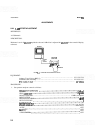
24. Set RESOLUTION
BW
control to 100
kHz.
Jumper A9TP6 to A9TP8. This forces the
BW7
line to
+
15Y Set
FREQ
SPAN/DIV to 100
kHz.
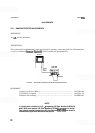
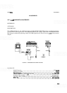
NOTE
When Bandwidth Filter Assemblies
All and A13 are installed with covers in
place, midget copper alligator clips (HP Part Number 1400
-
0483) can be used
to short test points to the cover.
25.
Perform preliminary LC filter adjustments
as
follows:
NOTE
It might be necessary to adjust the REF LEVEL
FINE control to obtain an on-
screen display during the following adjustments.
Remove A! 3 cover and install A13 on extender board.
Short to ground the following test points:
A13TP6, A1 1TP3, and A11TP6. (This widens
all
but one
LC pole).
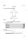
Center signal on CRT with TUNING control. Adjust
A13C73 for minimum signal amplitude.
Disconnect short from
A13TP6 and short to ground A13TP3.
Adjust A13C74 for minimum signal amplitude. Remove shorts from A13TP3, A1 lTP3, and
A1 1TP6.
Reinstall A13 and cover. Short A13TP3 and A13TP6 to ground. Remove A1 1 cover and install All
on extender board.
Short A1 1TP6 to ground.
Adjust A1
1C73 for minimum signal amplitude.
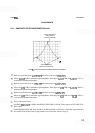
Disconnect short from
A1 1TP6 and short to ground A1 lTP3.
Adjust A1 1C74 for minimum signal amplitude.
Disconnect shorts from test points and reinstall
A1 1 and cover. Leave jumper from A9TP6 to A9TP8
in place.