


MODEL 8559A SERVICE
Band Offset
(D)
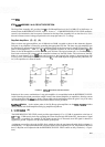
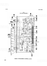
Operational amplifiers U4a, U4d, U4c, and their associated circuits provide offset and gain for the tilt voltage.
Potentiometers R57, R58, R59,
R60, R61, and R62 are used to adjust the offset of each band. A fixed negative
offset is provided for all bands by operational amplifier
U4c. The resulting flatness output voltage is applied to
a
voltage
-
controlled amplifier on Third Converter Assembly AlO.
Mixer Diode Bias (B)
Bias of the First Mixer Assembly A4 depends on the desired harmonic mixing number. Quad switch U1 and
operational amplifiers
U2a, U2b, and U2c with their associated components form the mixer diode bias sources.
Varying power levels are coupled into the mixer diode due to irregularities in the
YTO's swept power output,
causing variations in the mixer diode bias conduction angle, or total bias power. The bias sources adjust to these
instantaneous changes in the mixer bias conduction angle by increasing or decreasing bias in order to maintain a
constant conduction angle. The circuit includes separate bias adjustments for bands 2
-
,
2
+
,
3
-
,
and
3
+
.
Bands 1
-
and 1
+
use a common bias adjustment potentiometer.
The four switches in
U1
are normally closed, but the individual switches open when selected by a logic
-
high
control voltage. Since the outputs from the band select decoder U3 are all high except one, the normal status of
the switches in
U1 is open until a low control input allows one to close. The switch then connects one of the
three potentiometers
(R70, R71, R72) through a factory selected fixed resistor to the positive input (pin 10) of
operational amplifier
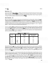
U2c, forming a voltage source at that point. The table below shows which potentiometers
and factory selected resistors apply to which band.
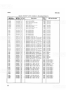
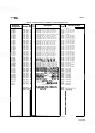
TABLE8-9. MIXER DIODE BIAS ADJUSTMENTS
Operational amplifier U2c forms a negative impedance converter that increases or decreases bias as needed to
maintain a constant angle of conduction at the first mixer. This is necessary to maintain a constant insertion loss
through the first mixer. Operational amplifier
U2c is connected to the voltage source at the junction of R73,
R74, R75, and
Q1. This circuit multiplies its input source resistance by approximately
-
1/110, thus converting
the input voltage source and series resistance into an equivalent voltage source and negative impedance (here,
approximately
-
1000 ohms).
Band
.01-3
6
-
9
3
-
9
9
-
1
5
6
-
15
12.1
-
21
Because of this conversion, as current increases in the circuit, the resultant output voltage decreases, just as it
would if a negative resistance value
(
-
R) were substituted for R in the familiar expression for Ohm's Law. The
expression would then be rewritten as:
E
=
I(
-
R). Notice now that an increase in current (I) results in a
decrease in voltage
(E).
This is the equivalent action of this circuit. If
all
of Ul's switches are open (as in band
2
-
or 2+), transistor Q1 forces the junction positive, turning off CR15 and thereby removing the negative
impedance converter from the bias output at P1
-
24. One of the other operational amplifiers in U2 is activated,
providing voltage sources and positive resistances to the bias output
(TPl or PI-24). When one
of
the opera
-
tional amplifiers is selected, the diodes at the outputs of the other two are reverse biased, and disconnect the
outputs from
PI-24.
8145
Control Name
V 1
V 1
V2
-
V2+
V3-
V3+
Bias Adjust
Resistor
R7
2
R7
2
R83
R87
R7
1
R7
0
Range Adjust Resistor
(Factory
-
Select)
R7
3
R7
3
R84
R8 8
R74
R7
5