


SERVICE MODEL 8559A
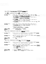
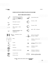
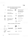
SYMBOLS USED IN SCHEMATICS AND BLOCK DIAGRAMS
BASIC COMPONENT SYMBOLS
Connection symbol
indicating a Jack (except for
PC board edge connectors)
Connection symbol
indicating a Plug (except for
PC
board edge connectors)
Test Point: Terminal
provided for test probe.
Measurement Point: Used to
indicate a convenient point
for measurement. No
terminal provided for test
probe.
(946)
Indicates wire or cable color
code. Color code same as
resistor color code. First
number indicates base color,
second and third numbers
indicate colored stripes.
4
Earth ground
6
Instrument chassis ground.
May be accompanied by a
number or letter to specify a
particular ground.
Q
Screwdriver adjustment
\
Q,
Front
-
panel control
\
Jumper wire
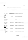
COMMONLY USED ASSEMBLY AND CIRCUIT SYMBOLS
0
Oscillator
@
-
Mixer
Jzf'
Tuneable cavity
T
L
--c_1
Transmission Line
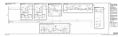
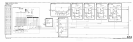
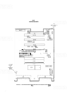
FIGURE
81.
SYMBOLS USED IN SCHEMATIC AND BLOCK DIAGRAMS
(2
OF
4)