


MODEL
8559A
SERVICE
RF SECTION CIRCUIT DESCRIPTIONS
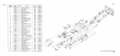
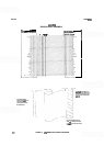
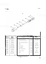
List of parts included in RF Section.
INPUT ATTENUATOR ASSEMBLY A3, CIRCUIT DESCRIPTION
The HP 8559A Input Attenuator Assembly A3 is a 50 ohm, precision, coaxial step attenuator. Attenuation in
10-dB steps from
0
dB to 70 dB is accomplished by switching the signal path through one or more of three
resistive pads in a predetermined sequence by the INPUT
ATTEN control. The Input Attenuator Assembly A3
is not field serviceable.
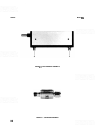
FIRST MIXER ASSEMBLY A4, CIRCUIT DESCRIPTION
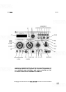
The First Mixer Assembly A4 is a sealed microcircuit (shown in Figure 8-19), that is not field serviceable and
must be replaced with either a new or factory rebuilt unit. In the mixer assembly, the
-01 to 21 GHz input signals
are combined with the first LO signal (3.01 to
6.04 GHz) generated by the YIG-Tuned Oscillator Assembly A6.
Fundamental mixing is used for the two lowest mixing bands, while harmonic mixing is used for the remaining
four bands. Fundamental mixing produces the sum and difference frequencies of the input and the LO fre-
quency. The fundamental mixing equation is:
F,
=
F,,
-t
F,,.
Where:
F,
=
signal frequency
F,,
=
local oscillator frequency
F,,
=
intermediate frequency
Harmonic mixing alters the mixing equation as shown:
F,
=
NF,,
-t
F,,
Where:
N
=
the harmonic number
An alternate first IF is used to eliminate the problem of IF feedthrough (baseline lift) that occurs when a signal
of the same frequency as the IF frequency
(3.0075 GHz) is present at the input. The second LO frequency is
lowered by 15 MHz (from 2.6861
GHz to 2.671
1
GHz) to establish the alternate first IF at 2.9929 GHz. The
first LO is also shifted to keep the signal on screen. The shift equation is:
15MHz
Frequency Shift
=
+
N
Where:
N
=
the harmonic number
A
17
-
23 MHz bandpass filter, in the Second Converter Assembly A5 housing, follows the first IF and is
centered at 3
GHz. The wide bandpass accommodates signals in either the regular or alternate IF modes.
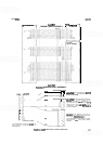
A schematic of the First Mixer Assembly A4 is shown in Figure 8-25. The output of the YTO is coupled into the
signal path ahead of the internal mixer. Mixing diode bias is supplied from the Step Gain Assembly A12. A
different bias current is used for each harmonic to minimize conversion loss and flatness problems. In addition
to mixer bias, the First Mixer Assembly A4 requires a
+
14.5V and
-
10V to power and bias the transistor
buffer amplifier at its output. Conversion loss of the mixer is about
-
12 dB.
8
-
51