


MODEL 8559A SERVICE
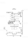
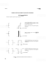
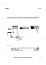
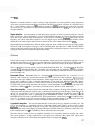
Nominal power levels, voltages, and waveforms shown on schematic diagrams were measured using
the test setup shown below. Note that signal characteristics shown on schematic diagrams are pro
-
vided as a troubleshooting aid only. They should not be used for making instrument adjustments.
Dl SPLAY
MA
l
NFRAME
-
OSCILLOSCOPE
DIGITAL VOLTMETER
L
1,
BLANK
I
NO
SPECTRUM ANALYZER
l
NPUT
EXTENDER
CABLE
EQUIPMENT:
Oscilloscope (with 10:
1
probe)
.....................................
HP 1741A
Spectrum Analyzer
.................................................
8569B
Digital Voltmeter
.................................................
HP 3456
Extender Cable Assembly
.....................................
HP 5060
-
0303
Adapter, Type N to BNC
(2
required)
............................
HP 1250
-
0780
FIGURE
8-2.
CONDITIONS FOR SCHEMATIC DIAGRAM MEASUREMENTS
(1
OF
2)