


PERFORMANCE TESTS
PERFORMANCE TESTS
MODEL 8559A
4
-
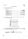
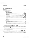
20.
GAIN
COMPRESSION
(Cont'd)
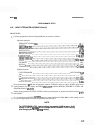
PROCEDURE:
1.
Set equipment controls as follows:
Spectrum Analyzer:
FREQUENCYBANDGHz
..................................................
.01-3
..............................................................
TUNING 0.050GHz
FREQ SPAN/DIV
.........................................................
100 kHz
RESOLUTION BW
..............................................
300 kHz, uncoupled
INPUTATTEN
.............................................................
10dB
REFERENCE LEVEL
....................................................
-
10 dBm
...........................................................
REFLEVELFINE
-
10
Amplitude Scale
........................................................
10 dB/DIV
SWEEP TIME/DIV
........................................................
AUTO
SWEEPTRIGGER
.....................................................
FREERUN
ALT IF ..................................................................... OFF
.................................................................
SIGIDENT OFF
....................................................................
BLCLIP OFF
.............................................................
VIDEOFILTER OFF
Signal Generator:
COUNTERMODE
...........................................................
INT
AM
........................................................................ OFF
FM
........................................................................
OFF
FREQUENCYTUNE
......................................................
50MHz
RF
..........................................................................
ON
........................................................
OUTPUTLEVEL -4dBm
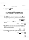
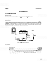
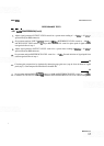
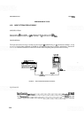
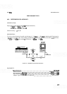
2.
Connect equipment as shown in Figure
4
-
16.
Note that the 10-dB attenuator is placed between the power
splitter and spectrum analyzer INPUT
5(M2 connector.
3.
Adjust signal generator OUTPUT LEVEL control for a power meter reading of
-
10 dBm (
-
20 dBm at
spectrum analyzer INPUT
5(X2 connector).
4. Adjust spectrum analyzer TUNING control to center 50 MHz signal on CRT. Set Amplitude Scale control
to 1
dB/DIV and adjust REF LEVEL FINE control to place peak of signal at a convenient horizontal
graticule line other than top graticule line.
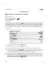
5.
Adjust signal generator OUTPUT LEVEL control for a power meter reading of 0 dBm
(
-
10 dBm at
spectrum analyzer INPUT
5(M2 connector).
6.
Set spectrum analyzer REFERENCE LEVEL control to 0 dBm, leaving REF LEVEL FINE control at
setting established in step 4. Record deviation of signal peak from reference graticule line of step 4
(step-
gain error). Values above reference line are positive
(
+
);
those below are negative
(
-
).