


MODEL 8559A ADJUSTMENTS
ADJUSTMENTS
5
-
21.
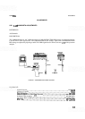
BANDWIDTH FILTER ADJUSTMENTS (Cont'd)
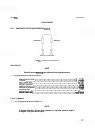
26.
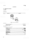
Short to ground
A1 lTP3, A1 lTP6, and A13TP3. Set RESOLUTION BW to 100 kHz and set FREQ
SPAN/DIV to 20 kHz.
27.
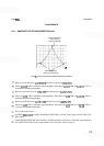
Center signal on CRT with TUNING control. Adjust
A13C45 LC CTR for symmetrical bandpass display
on
CRT Use FINE TUNING control to keep crystal spike centered.
NOTE
The crystal spike represents the center frequency of the crystal poles. In
this procedure we are aligning the LC poles with the crystal poles. On some
instruments, the crystal spike may not be very pronounced, in which case
the center frequency of the
100
kHz RBW will have to be compared to the
center frequency of the
30
kHz RBW.
28. Move short from A13TP3 to A13TP6. Leave other shorts in place. Center signal on CRT with TUNING
control. Adjust
A13C23 LC CTR for symmetrical bandpass display on CRT, keeping crystal spike cen
-
tered.
29.
Move short from
A11TP6 to A13TP3. Leave other shorts in place. Center signal on CRT with TUNING
control. Adjust
A1 lC45 LC CTR for symmetrical bandpass display on CRT, keeping crystal spike cen
-
tered.
30.
Move short from
A1 1TP3 to A1 1TP6. Leave other shorts in place. Center signal on CRT with TUNING
control. Adjust A1
1C23 LC CTR for symmetrical bandpass display on CRT, keeping crystal spike cen
-
tered.
31. Disconnect shorts from
A1 1TP6, A13TP3, A13TP6, and from ground. Remove jumper from A9TP6 and
A9TP8.
32.
Set FREQ
SPAN/DIV to 10 kHz and RESOLUTION BW to 30 kHz. Center signal on
~RT
with TUN
-
ING control. Set RESOLUTION BW to 100 kHz and note where signal crosses center vertical graticule
line.
33. Adjust A1
lC23, A1 1C45, A13C23, and A13C45 in succession so that amplitude of signal is peaked where
it crosses center vertical CRT graticule line, repeating step 32 between adjustments
as
necessary.
34. Repeat steps 32 and 33 until 30 kHz and 100 kHz bandwidths are centered with each other. If signal shift
between 30 kHz and 100 kHz bandwidths is greater than 10 kHz (1 division), repeat steps
24
through 33.
Bandwidth Amplitude
35. Set Amplitude Scale switch to 1 dB/DIV and jumper A9TP6 to A9TP8.
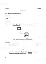
36.
Short
A1 1TP3, A1 lTP6, A13TP3, and A13TP6 to ground.
37. Set RESOLUTION BW to 100 kHz and FREQ
SPAN/DIV to 200 kHz.