


MODEL
8559A
PERFORMANCE TESTS
PERFORMANCE TESTS
4
-
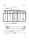
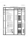
26.
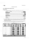
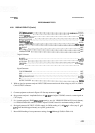
DISPLAY FIDELITY
(Cont'd)
FREQ SPAN/DIV
.........................................................
500 kHz
RESOLUTION BW
..............................................
300 kHz, uncoupled
INPUT
ATTEN
.............................................................
10 dB
REFERENCE LEVEL
.......................................................
0 dBm
..............................................................
REFLEVELFINE 0
..............................................................
Amplitudescale LIN
SWEEP
TIME/DIV
........................................................
AUTO
SWEEPTRIGGER
.....................................................
FREERUN
..................................................................... ALTIF OFF
SIC IDENT
.................................................................
OFF
BL CLIP
....................................................................
OFF
VIDEO FILTER
............................................................. OFF
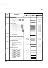
Digital Voltmeter:
.....................................................................
RANGE 100
FUNCTION
...............................................................
v
PC)
AUTO CAL
...............................................................
AUTO
............................................................
TRIGGER INTERNAL
MATH
.....................................................................
OFF
Signal Generator:
........................................................... COUNTERMODE INT
........................................................................
AM
OFF
........................................................................
FM OFF
......................................................
FREQUENCYTUNE 30MHz
..........................................................................
RF ON
OUTPUT LEVEL
..........................................................
0 dBm
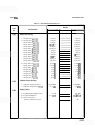
2.
With no signal at spectrum analyzer's INPUT 5052, measure and record offset voltage at (AUX A) VERTI
-
CAL OUTPUT connector.
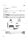
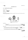
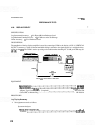
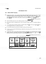
3. Connect equipment as shown in Figure 4
-
22. Set step attenuator to 0 dB.
4.
Set spectrum analyzer's Amplitude Scale to 10 dB/DIV and adjust TUNING control to center signal on
CRT display.
5. Set spectrum analyzer's FREQ
SPAN/DIV control to zero (0), VIDEO FILTER full CW (not in detent),
and RESOLUTION BW control to 1 MHz. Adjust TUNING control for maximum reading on DVM.
6.
Set signal generator OUTPUT LEVEL control for DVM reading of
(+
800 mV
+
offset (step 2)
f
0.5
mV). Trace should be approximately at top CRT graticule line.
7.
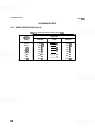
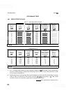
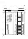
Record DVM readings for step attenuator settings, from
0 dB through 70 dB, in Table 4-16.