


MODEL
8559A
SERVICE
THE HP 8559A SPECTRUM ANALYZER THEORY OF OPERATION
General Information
The HP 8559A is a wideband spectrum analyzer plug-in module for use with either the HP 180 series or HP
853A display mainframes. It tunes from 10 MHz to
21
GHz and displays frequency spans as wide as 9 GHz (in
bands 5 and 6) and as narrow as
100 kHz (in band 1). A zero span feature enables the analyzer to operate as a
tunable, fixed-frequency receiver. Resolution bandwidths of 3 MHz to 1 kHz are selectable in a 1-3-10 sequence.
CRT display calibration can be maintained by coupling the frequency span, resolution bandwidth, and video
filter to an automatic sweep time control. A five-LED numerical display allows direct readout of the display
center frequency or the tunable marker frequency.
The adjustable reference-level control is calibrated to allow direct readout of amplitudes ranging from
-
11 1 to
+
30 dBm. Continuous wave (CW) signals at or below the Reference Level, the top display graticule, are
automatically below the analyzer's gain compression specification. Dynamic range is greater than 70 dB.
The resolution bandwidth and frequency span controls can be locked together to function as a
"
zoom
"
control.
Signal identification, in spans from
100 kHz to 10 MHz per division, and an alternate IF are also available. This
latter feature eliminates problems caused by IF feedthrough (baseline lift) and allows measurement of all signals
within the frequency range of the analyzer.
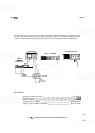
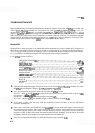
The typical spectrum analyzer comprises three main sections (see Figure 8-3): the RF section, the IF section, and
the display section. Since it is a plug-in designed to work with a display mainframe, the HP
8559A houses only
the RF and IF sections. The display and power supply are contained in the mainframe.
RF Section
The HP 8559A RF section resembles a triple-conversion superheterodyne receiver; input signal frequencies are
converted three times before processing for display. Triple conversion makes possible wide frequency coverage
and permits filtering and amplification at more easily controlled frequencies.
RF Attenuator.
The stepped RF Input Attenuator Assembly A3, at the input to the
RF
section, attenuates
the input in precise 10 dB steps from
0 to 70 dB. Precise and repeatable attenuation and gain in the signal path
are necessary to preserve amplitude calibration and direct reading of signal amplitudes on the CRT.
RF
attenua-
tor adjustment establishes the optimum signal level applied to the First Mixer Assembly A4.
First Mixer.
Within the First Mixer Assembly A6, the incoming signal mixes with the first local oscillator,
generating the first
IE
The first converter consists of a single microwave diode, a 4.8 GHz Low-Pass Filter
Assembly
FLl contained in a short RF cable, and
-
housed in the Second Converter Assembly A5
-
a 3 GHz
bandpass filter with a 17 to 23 MHz bandwidth.
First LO.
A YIG-Tuned Oscillator Assembly A6, or YTO, is used as the first LO. YIG, yttrium-iron-garnet,
is a ferro-magnetic material which is polished into a small sphere and precisely oriented in a magnetic field.
Changes in this magnetic field alter the frequency generated by the YTO. For the YTO in the HP
8559A, a
frequency range of 3.01
GHz to 6.04 GHz is used. Voltage control of the magnetic fieId surrounding the YIG
sphere allows the analyzer to be swept or tuned within these frequency limits. A control voltage, derived from
the sweep generator, tunes the YTO in sync with the horizontal deflection of the CRT beam. A tuning voltage
offsets the sweep to establish the center frequency. Voltage control of the analyzer's frequency is convenient,
since low frequency circuits, like operational amplifiers and transistors, can generate and modify the control
voltage.
Second Converter.
The Second Converter Assembly A5 houses the 3 GHz bandpass filter, the second mixer,
and the second
LO.
The 3 GHz filter uses the resonant characteristics of three precisely machined cavities, or
8-9