


MODEL
8559A
SERVICE
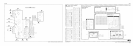
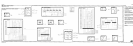
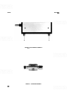
SECOND CONVERTER ASSEMBLY A5, CIRCUIT DESCRIPTION
The IF from the First Mixer Assembly A4 is coupled into the Second Converter Assembly A5 bandpass filter
through coupling loop L3. Three circular, slug
-
tuned cavity resonators, operating as an inductive transmission
line, make up the
bandpass filter. The filter forms a high
-
Q circuit centered at 3 GHz with a 23 MHz bandwidth
that is required to accommodate the regular and alternate
IFs. Coupling loops L4 and L5 provide coupling
between the cavities. Loop coupling is also used to couple the
3
GHz IF signal to the second LO output at the
mixer diode
CR1.
The second LO contains varactor diodes that are controlled by a voltage from the Marker Assembly A8. The
diodes shift the frequency of the second LO either 15 MHz (ALT IF) or
+
1 MHz (SIG ID). The varactor
control voltage is always between
1V and 28V and corresponds to the oscillator frequency; increasing the
voltage increases the frequency.
Both the second LO and the 3
GHz
IF
signal are coupled into mixing diode CR1, generating a difference
frequency of 321.4 MHz that is coupled through the matching filter (C3, L2, C4) to the Third Converter
Assembly
AlO. The matching filter is a passive network designed to match the impedance of the second mixer
to the 50 ohm impedance of the Third Converter Assembly
A10. The match is optimized in both IF modes by
adjusting L2 (2nd MIXER MATCH).
SECOND CONVERTER ASSEMBLY A5, TROUBLESHOOTING
Verify that the Second Converter Assembly A5 supply voltages are correct.
If the displayed signal amplitude varies between ALT IF and REG
IF,
perform and verify the bandpass and
second LO frequency adjustments.
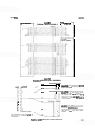
Second LO Frequency:
A failure in the Second Converter Filter Assembly A5A2 can cause the Second
Converter Oscillator
A5A1 to oscillate at about 3
GHz.
This symptom can occur when the delay circuit in the
filter assembly does not delay the application of the
+
13V bias voltage. To test the delay, observe the
+
13V
bias as the instrument is turned on. There should be a noticeable delay before the
+
13V is applied to the line.
The
-
10V supply, on the other hand, should rise gradually. If the
+
13V and the
-
10V respond properly, check
the varactor voltage, varactor diodes, and the cavity adjustment as the possible source of the second LO
frequency error.
Second LO Fails to Oscillate:
The Second Converter Oscillator Assembly A5A1 can intermittently fail to
oscillate after turn
-
on. If this symptom occurs, replace the entire assembly. Before removing the defective circuit
board, note the orientation of components, leads, and hardware; orientation is critical to proper operation. To
prevent damage to the replacement circuit board, do not over
-
tighten the hex
-
head antenna screw during instal
-
lation.
Second Converter Bandpass Shape:
Low signal power from the First Mixer Assembly A4 can distort the
second converter
bandpass filter shape. Excessive ripple in the bandpass can be the result of a mismatch in the
signal path preceding the Second Converter Assembly A5. An input attenuator setting of
0 dB can cause such a
mismatch. The second converter mixer diode or Mixer Match adjustment can also affect the
bandpass ripple.
Residual
FM:
Residual
FM
can originate from the Marker Assembly A8 Second LO Driver, which supplies
the varactor bias voltage, or from within the second LO itself.
8-53