


MODEL
8559A
SERVICE
k.
Use a no. 4 hex wrench to firmly tighten both set screws in front Anticrush Drive Hub (7). Recheck
Ref Level Shaft (6) as in step j, and readjust front Anticrush Drive Hub as necessary.
1.
Slip Miter Gear (51) over Attenuator Shaft Assembly (18). Do not tighten at this time.
m.
Inspect Ref Level Fine Assembly (30, 3 1, 65
-
69). Ref Level Fine Shaft (65) should turn smoothly.
Check Ref Level Fine Potentiometer (69) and connecting wires for good electrical connections.
Lightly grease Ref Level Fine Shaft and hollow Index Disc Locator (64) shaft.
n.
Install Index Disc Locator
(64)
on Front Switch Assembly. Hole in locator bar rides over left-most
Standoff (62) used to support Ref Level Fine Pot Plate (68). Install Ref Level Fine Assembly (30, 3 1,
65
-
69) on Front Switch Assembly with three Screws (48). Connecting wires should be routed. Ref
Level Fine Shaft (65) should turn smoothly without binding over its full rotation. Adjust position of
Ref Level Fine Pot Plate as necessary.
o. Use a new
tiewrap to attach Ref Level Fine connecting wires to Standoff (62).
6.
Installation of RF Input Attenuator A3:
a.
Mount RF Input Attenuator to Attenuator Bracket (49) using two Screws (48). Check all eight
attenuator positions by hand for proper detent action and smooth operation. Leave attenuator in full
counter
-
clockwise position.
b. Slide Miter Gear (51) to end of Attenuator Shaft Assembly (18) against Ref Level Fine Pot Plate (68).
Set Attenuator Assembly in place on Front Switch Assembly, with notch in Attenuator Bracket (49)
lightly greased and aligned with Attenuator Shaft Assembly. Use Washer (50) and Screw (45) to fasten
Attenuator Bracket to lower left corner of Front Switch
Diecast (1). (Do not tighten Miter Gear at
this time.)
7. Installation of Front Panel:
Remove the front panel knobs.
Use a
5/16-inch nut driver and two hex nuts to carefully install front panel (with pushbutton bezels
and DPM window installed) on Front Switch
Diecast
(1).
Insert RF Input Cable Assembly W1 through front panel and loosely attach with hex nut. Carefully
connect cable assembly to
RF
Input Attenuator using a 5/16-inch open
-
end wrench. Tighten cable
assembly to front panel using a
5/8-inch open-end wrench.
Use a no. 4 hex (Allen) wrench to install lock Knob on Locking Shaft (3). Base of Lock Knob should
clear front panel when Locking Shaft is pushed in.
Install front panel nut and washer on Coarse Tune Bushing and tighten with special
1/2-inch nut
driver.
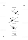
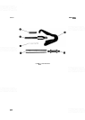
NOTE
Front
-
panel control knobs and their attaching parts are identified in Figure
6-1.
Numbers in parentheses match numerical callouts on Figure
8-1
0.