


SERVICE
MODEL
8559A
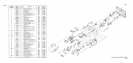
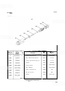
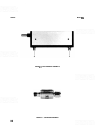
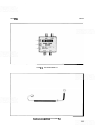
FIRST MIXER ASSEMBLY A4, TROUBLESHOOTING
Typically, a bad first mixer results in at least a 15 to 20 dB loss in sensitivity (i.e., the amplitude of displayed
signals is
15 to 20 dB low). There are, however, other factors that can affect spectrum analyzer sensitivity that
should be checked. The measurement of power levels along the signal path can give a good indication of where
the loss is occurring. The output of the Second Converter Assembly A5 offers a convenient point to isolate the
RF front
-
end from the IF section. If the loss appears to be in the front
-
end, measure the power levels of the first
and second local oscillator with a second spectrum analyzer. Next, measure the supply and bias voltages at the
first mixer. To access the push
-
on connectors of the first mixer's bias and supply lines, it is helpful to remove the
instrument's bottom guide
-
rail.
The First Mixer Assembly A4 can be damaged by electro
-
static discharge.
Tools and hands should
be
grounded before handling this assembly. It is
also possible to damage the mixer diode with an ohmmeter. Damage may
occur with as little as
3V
open-circuit-voltage between the ohmmeter
probes. Therefore, dc testing of the assembly is not recommended. If it
becomes necessary to remove the rigid coaxial cable connecting the first
mixer output and the second mixer input, be careful not to damage the Low
Pass Filter Assembly
FL1 internal to the cable. The filter assembly is very
sensitive to bending.
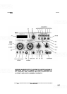
Set HP 8559A controls as follows:
FREQUENCYBANDGHz
..................................................
.01-3
TUNING
...............................................................
.035GHz
FREQSPAN/DIV
..........................................................
]MHz
RESOLUTIONBW
.........................................................
lMHz
.............................................................
INPUT A'ITEN 10 dB
REFERENCELEVEL
.....................................................
-10dB
REFLEVELFINE
..............................................................
0
Amplitudescale
.........................................................
ldB/DIV
........................................................
SWEEP TIME/DIV AUTO
SWEEPTRIGGER
.....................................................
FREERUN
VIDEOFILTER
.............................................................
OFF
BLCLIP
....................................................................
OFF
SIGIDENT
.................................................................
OFF
ALTIF
.....................................................................
OFF
Connect the CAL OUTPUT signal to the RF INPUT
NOTE
Before making the following adjustments, measure and note the first mixer
bias voltage
(A16TP1). This permits the instrument to be returned to calibra
-
tion if the first mixer is good.
Adjust the V1 potentiometer (A12R72 on the Step Gain Amplifier Assembly A12) through its range and
observe the changes in the displayed signal peak and the bias voltage. With
a
good mixer, two changes are
observed: the displayed signal peaks at some point in the adjustment (usually with about
-
5V or
-
6V of bias
voltage) and the bias voltage
(A16TPI) ranges from
-
9V to
+
2
k
0.5Y If
all
of these characteristics are not
present, the mixer is probably damaged.