


ADJUSTMENTS
MODEL
8559A
ADJUSTMENTS
5
-
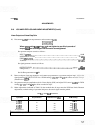
21. BANDWIDTH FILTER ADJUSTMENTS (Cont'd)
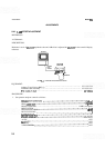
Center the signal with TUNING control. Using REF LEVEL FINE control, place signal peak at 7.1
divisions (0.9 division from top graticule line).
Adjust
A9R85 LC until signal is five divisions wide at the fifth graticule line
(1
MHz wide at 3
-
dB points).
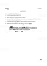
Set FREQ
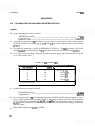
SPAN/DIV to 10 kHz and RESOLUTION BW to 10 kHz.
Center the signal with FINE TUNING control.
Using REF LEVEL FINE control, place signal peak at
7.1
divisions.
Adjust
A9R72 XTL until signal is one division wide at the fifth graticule line
(10
kHz wide at 3
-
dB points).
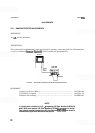
Set FREQ
SPAN/DIV to 20 kHz and RESOLUTION BW to 30 kHz.
Center signal with TUNING control.
Adjust REF LEVEL FINE control to place signal at sixth graticule line.
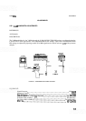
Remove top guide rail. Connect crystal shorts (through cover access holes) across the following pairs of
test points:
A13TPl/TP2, A1 1TPl/TP2, and A1 lTP4/TP5.
NOTE
Keep crystal spike centered during adjustments. The SYM and CTR adjust
-
ments for each crystal interact (the signal also drifts in this narrow span).
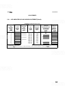
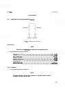
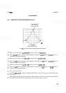
13.
Adjust front
-
panel TUNING control to center bandpass spike (Figure 5
-
7) on the CRT display.
NOTE
A
non-metallic tuning tool is required for adjustments on the All and A13
bandwidth filter assemblies.
14.
Adjust
A13C54 CTR for minimum signal amplitude. Then adjust A13C38 SYM and A13C54 CTR for a
centered and symmetrical
bandpass as shown in Figure
5
-
7.