


ADJUSTMENTS
MODEL
8559A
ADJUSTMENTS
5
-
29.
CAL OUTPUT AND REF LEVEL CAL ADJUSTMENTS
NOTE
These adjustments should be followed by frequency response adjustments,
since adiustment of
A12R57 1A (offset) will shift the freauencv resDonse of
Band
1
(.bl
-
3
GHz).
REFERENCE:
A10 and A12 Schematics
DESCRIPTION:
The 35 MHz CAL OUTPUT signal is adjusted for proper amplitude and frequency using a power meter and
frequency counter. Adjustment range of the front
-
panel REF LEVEL CAL control is set using the CAL OUT
-
PUT signal as a reference.
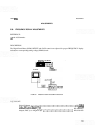
EQUIPMENT:
Dl SPLAY
SPECTRUM
ANALYZER
M
I
CROWAVE
POWER COUNTER
METER
;;; ;;;
0
000
000
-
.
0
0
a00
0
l
NPUT
@.@@6
'-jnlPuT
OUTPUT
1
!Kk
ADAPTER
I---;---
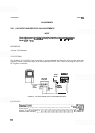
FIGURE 5
-
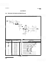
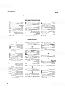
20.
CAL OUTPUT AND REF LEVEL CAL ADJUSTMENTS TEST SETUP
.......................................................
FrequencyCounter HP5342A
Power Meter
.....................................................
HP 432A/435A/B
Power Sensor
...........................................................
HP 8481A
Adapter, Type N (m) to BNC
(f)
.........................................
HP 1250
-
0780
Extender Cable Assembly
..............................................
HP 5060
-
0303