


MODEL 8559A ADJUSTMENTS
ADJUSTMENTS
5
-
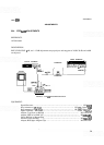
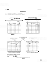
26. SECOND CONVERTER ADJUSTMENTS
REFERENCE:
A3, A4,
AS, A6, and A8 Schematics
DESCRIPTION:
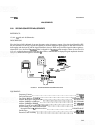
First, the Second LO is adjusted for proper frequency using a frequency counter. Next, the signal identifier (SIG
ID) and alternate IF (ALT IF) signals are adjusted so that the displayed signal appears in the same location in
both regular and alternate IF and the signal identifier is always 1 MHz away from this signal
in
either regular or
alternate IF. Last, the first IF
bandpass filter is
aligned
for a bandpass wide enough to allow for the first LO
shift and amplitude characteristics such that there will be a minimal shift in displayed signal amplitude when the
analyzer is switched from regular to alternate
IF.
Dl SPLAY
FUNCT ION
QENERATOR
0:
:
.000
[q!
OUTPUT
M
I
CRWAVE
COUNTER
000 000
-
0
0 000
0
ADAPTER TEST
TER
A5A2Pl A5J9
ADAPTER
VARACTOR
2ND
LO
\
'O=ri
SPECTRUM
@.@a@
ANALYZER
OUTPUT
u
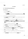
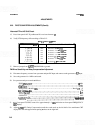
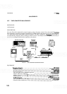
FIGURE 5
-
12.
SECOND CONVERTER ADJUSTMENTS TEST SETUP
EQUIPMENT:
Frequency Counter
.......................................................
HP 5342A
Function Generator
......................................................
HP 33 10A
Test Cable, BNC (m) to SMB
(f)
.......................................
HP 85680
-
60093
Adapter, BNC
(f)
to Alligator Clips
......................................
HP 8120
-
1292
Adapter, SMB (m) to SMB (m)
..........................................
HP 1250
-
0669
Adapter, SMB
(f)
to SMB
(f)
............................................
HP 12%0672
Adapter, Type N
(m)
to BNC
(f)
(2 required)
...............................
HP 1250780
Special Tuning Tool, Allen driver inserted
through drilled
-
out 5/ 16 inch nut driver
...............................
HP 08555
-
60107
Oscilloscope
............................................................
HP1740A
Extender Cable Assembly
..............................................
HP 5060-0303