


SERVICE
MODEL
8559A
output to the mainframe,
44
must receive a positive voltage. The Blanking Driver
is
driven
by
the Vertical/
Baseline Comparator and the Sweep Ramp High/Low Limit Comparator. Either of these circuits can produce
the positive input needed by the Blanking Driver to produce a blanking output.
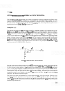
Penlift Driver (G)
The display is blanked during retrace and during the dead time of the sweep ramp. Retrace blanking from the
Sweep
Generator/Bandwidth Control Assembly A9 is applied to the emitter of the buffer amplifier Q1. When
the sweep ramp is turned off (dead time), the retrace blanking signal rises to
+
101 This voltage appears at the
base of
Q4,
blanking the display. Simultaneously, the
+
10V signal is applied to base of Q5, causing the collector
of
Q10 to rise to
+
15Y Transistor Q10 provides the signal used to lift the pen of the
X
-
Y
recorder during the
analyzer's sweep retrace and dead time. Zener diodes
VR2
and VR3 limit the output to 35V to protect Q10 from
high voltage and inductive transits generated by the
X
-
Y
recorder.
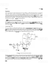
Sweep Indicator Driver (H)
The front panel SWEEP indicator lights when the retrace blanking signal is low (OV). Transistor 422 is turned
on by the low retrace signal and switches on the SWEEP light
-
emitting diode.
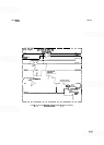
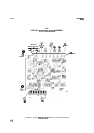
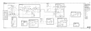
VERTICAL DRlVERlBLANKlNG ASSEMBLY A15, TROUBLESHOOTING
Display Held in Blanked Mode:
When this occurs, it may be necessary to increase the display intensity (on
HP
180 series mainframes) to make the trace visible. A bright dot appears at the beginning of the trace and the
BL CLIP control does not work. Most common failures are
48 and 416 (always change both).
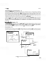
The S
+
T line from the Frequency Control Assembly
A7
can cause the comparators (block C) to latch
-
up.
The Sweep
Generator/Bandwidth Assembly A9 retrace line input line can lock
-
up retrace.
Display Offset in Linear:
Most common failure is
417.