


ADJUSTMENTS
ADJUSTMENTS
MODEL
8559A
5
-
19.
LOG AMPLIFIER LOG AND LINEAR ADJUSTMENTS (Cont'd)
PROCEDURE:
1. Set equipment controls as follows:
Spectrum Analyzer:
FREQUENCY BAND
GHz
..................................................
.0
1
-
3
TUNING
.............................................................
>O.OlOGHz
FREQSPAN/DIV
...............................................................
0
RESOLUTION BW
..............................................
300
kHz, uncoupled
INPUTATTEN
.............................................................
10dB
REFERENCELEVEL
....................................................
-50dBm
REFLEVELFINE
.............................................................
0
Amplitude Scale
..............................................................
LIN
SWEEP
TIME/DIV
........................................................
AUTO
SWEEPTRIGGER
.....................................................
FREERUN
ALTIF
.....................................................................
OFF
SIG IDENT
.................................................................
OFF
BLCLIP
....................................................................
OFF
VIDEOFILTER
............................................................
OFF
Signal Generator:
COUNTERMODE
...........................................................
INT
AM
........................................................................
OFF
FM
........................................................................
OFF
FREQUENCY TUNE
...................................................
321.4 MHz
RF
..........................................................................
ON
OUTPUTLEVEL
................................................
approx. -28dBm
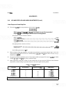
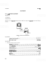
2. Set 1
-
dB step attenuator to 10 dB and 10
-
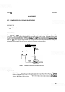
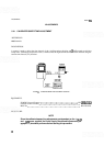
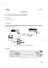
dB step attenuator to 0 dB. Remove AlOWl (blue cable) from
A5J2 and connect equipment as shown in Figure 5
-
3, using adapter to connect step attenuator to AlOWl.
NOTE
The HP 355C 10 dB attenuation is included to compensate for 10 dB of gain
on Step Gain Assembly A12 with the TEST
-
NORM switch in TEST.
3.
Set TEST
-
NORM switch on Step Gain Assembly A12 to TEST position. Adjust signal generator FRE
-
QUENCY TUNE control for maximum signal amplitude on display with 10-dB step attenuator set to
0
dB
(reduce signal generator OUTPUT LEVEL control setting as necessary to bring signal on
-
screen).