


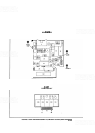
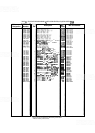
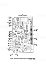

Figure
8
-
29.
Frequency Control Assembly
A7,
Schematic Diagram
(1
of
2)
(CO
G
~'~)
2004A
&
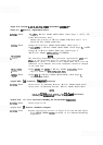
Below Make the following changes in function block (A):
Delete
R99.
Connect pin 7 of UlOB to pin 10 of U1OC.
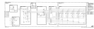
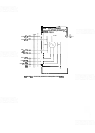
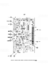
Figure
8
-
29.
Frequency Control Assembly
A7,
Schematic Diagrar
(2
of
2)
2236A
&
Below Replace Figure 8
-
29 (2 of 2) with new Figure 8
-
29 (2 of 2)
(SERIAL PREFIX 2236A) included in this Manual Backdating
supplement.
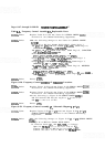
2208A
&
Below Make the following changes to Figure 8
-
29 (2 of 2) (SERIAL PREFIX
22368)
:
Change A7 to HP Part Number 08559
-
60021.
Replace function block
(El with P/O Figure 8
-
29 (SERIAL PREFIX
22088) included in this Manual Backdating supplement.
In function block
(GI,
delete C14 and R102.