


ADJUSTMENTS
5
-
21. BANDWIDTH FILTER ADJUSTMENTS (SERIAL PREFIX 1909A) (Cont'd)
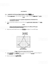
23. Carefully center signal on CRT in 30
kHz
RESOLUTION BW; then switch RESOLUTION BW to 100
kHz.
Note where signal intersects the center vertical graticule line.
24.
Adjust A13C45 LC CTR for
maximum
signal amplitude where the signal intersects the center vertical
graticule line.
25. Switch RESOLUTION BW to 30
kHz
and center signal; then switch to 100
kHz.
Note where signal
intersects the center vertical graticule line.
26.
Adjust A13C23 LC CTR for
maximum
signal amplitude where the signal intersects the center vertical
graticule line.
27. Switch RESOLUTION BW to 30
kHz
and center signal; then switch to 100
kHz.
Note where signal
intersects the center vertical graticule line.
28.
Adjust
A1 lC45 LC CTR for
maximum
signal where the signal intersects the center vertical graticule line.
29.
Switch RESOLUTION BW to 30
kHz
and center signal; then switch to 100
kHz.
Note where signal
intersects the center vertical graticule line.
30. Adjust
AllC23 LC CTR for
maximum
signal amplitude where the signal intersects the center vertical
graticule line.
3l.
Switch RESOLUTION BW between 100
kHz
and 30
kHz
to
be
sure the signal is centered at both band-
width settings.
Bandwidth Amplitude
32. Set Amplitude
Scale
to 1 dB/DIV and SWEEP TIMWDIV to AUTO.
33.
Set
RESOLUTION BW to 3
MHz
and FREQ SPAN/DIV to 50
kHz.
34.
Adjust fine TUNING and REF LEVEL FINE for
a
centered signal at 7 divisions.
35.
Set
RESOLUTION BW to 100
kHz
and center signal with fine TUNING control. Adjust A13R26 LC and
A1
1R26 LC equally to obtain a signal amplitude of 7 divisions.
36. Set RESOLUTION BW to 1
kHz
and FREQ SPAN/DIV to 10
kHz.
Center signal with fine TUNING
control. Adjust A1
1R31 XTL and A13R31 XTL equally for a signal amplitude of 7 divisions.
NOTE
Each potentiometer should
be
adjusted to accomplish half the necessary
increase in signal amplitude.