


ADJUSTMENTS
MODEL 8559A
ADJUSTMENTS
-
-
5
-
17.
POWER SUPPLY CHECKS AND ADJUSTMENTS
(Cont'd)
PROCEDURE:
1. Set spectrum analyzer controls as follows:
FREQUENCYBANDGHz
..................................................
.01-3
TUNING
..............................................................
0.010GHz
..........................................................
FREQ SPAN/DIV F (full)
...............................................
RESOLUTION BW Optimum, coupled
INPUTATTEN
.............................................................
10dB
.......................................................
REFERENCE LEVEL 0 dBm
REFLEVELFINE
..............................................................
0
........................................................
Amplitude Scale 10 dB/DIV
.........................................................
SWEEP TIME/DIV
MAN
SWEEPTRIGGER
.....................................................
FREERUN
ALTIF
.....................................................................
OFF
SIGIDENT
.................................................................
OFF
BLCLIP
....................................................................
OFF
VIDEOFILTER
.............................................................
OFF
NOTE
In all following adjustments, connect negative terminal of digital voltmeter
to spectrum analyzer chassis unless otherwise instructed.
2.
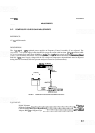
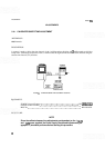
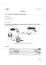
Connect equipment as shown in Figure 5
-
1. Install Frequency Control Assembly A7 on extender board
and connect digital voltmeter to
+
14.W test points A7TP3.
3. Adjust
+
14.5V potentiometer A7R41 for a voltmeter indication of
+
14.500 k0.002 Vdc.
4.
Connect digital voltmeter to
-
10V test point A7TP2 and adjust
-
10V potentiometer A7R29 for a volt
-
meter indication of
-
10.000
-t
0.005 Vdc.
5.
Use digital voltmeter to check for
-
12.0
+
0.
I
Vdc at collector (case) of transistor A7Q7, located near
center of Frequency Control Assembly A7. Vary MAN SWEEP control over entire range and verify that
voltage indication varies no more than
t
0.05 Vdc.
6.
Remove extender board and reinstall Frequency Control Assembly A7.