


MODEL
8559A ADJUSTMENTS
ADJUSTMENTS
5
-
25.
FIRST CONVERTER ADJUSTMENTS (Cont'd)
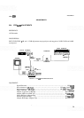
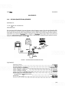
First LO Adjustments
2. Connect DVM to A7TP6
TUNE.
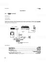
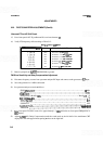
3. Set spectrum analyzer controls as follows:
INPUT
ATTEN
..............................................................
0 dB
FREQ
SPAN/DIV
...............................................................
0
ALTIF
.....................................................................
OFF
4.
Connect frequency counter to spectrum analyzer
RF
Input.
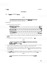
5.
Jumper
A16TPl DIODE BIAS to ground. A16TP1 is located on the motherboard through a hole in the
analyzer left side gusset.
6. Adjust front
-
panel TUNING control for DVM indication of 0.000 Vdc (fully counterclockwise).
7. Adjust
A7R8 (3 GHz) for frequency counter indication of 3.000 GHz
+
1 MHz. (If this adjustment cannot
be achieved, factory select resistor
A7R3* can be added
-
if it is not installed
-
or decreased to provide the
proper range. Select a value of 147K ohms for
A7R3*, initially, and decrease this value to no less than
56.2K ohms.)
8. Adjust front
-
panel TUNING control for DVM indication of
-
10.000 Vdc.
9.
Set A7R75 6 GHz F (fine) to approximately mid
-
range (R75 is a 20-turn potentiometer).
10. Adjust
A7R47 6 GHz C (coarse) for a frequency counter indication of 6.000 GHz
+2
MHz.
11. Retune front
-
panel TUNING control for 0.000 Vdc DVM indication and readjust A7R8 3 GHz if neces
-
sary for frequency counter indication of 3.000 GHz
*
1 MHz.
12.
The front
-
panel TUNING control for
-
10.000 Vdc DVM indication.
13. Lightly tap the top edge of the A7 Frequency Control board with the handle of
a
small screwdriver to seat
controls.
14. Adjust
A7R75 6 GHz F (fine) for frequency counter indication of 6.000 GHz
*
1
MHz.