


MODEL 8559A
INSTALLATION AND OPERATION VERIFICATION
2-1
4.
Graticule Overlays
2-1
7.
Operating Environment
2- 15.
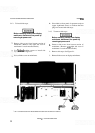
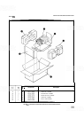
To install a graticule overlay:
1
Select proper overlay. HP Part Number
5020-
8565 is for HP 180TR display mainframes, HP
Part Number 5020
-
8566 is for HP 181T/TR
display mainframes, and HP Part Number
5020-8567 is for HP 182T display mainframes.
2. For HP
180TR and HP 181T/TR mainframes,
remove CRT bezel and metallic
-
mesh contrast
filter. Insert proper overlay and replace contrast
filter and CRT bezel.
3.
For HP l82T mainframes, grasp top portion of
CRT bezel and pull straight up. Remove metal
-
lic-mesh contrast filter and insert proper over
-
lay and contrast filter. (Either the metallic-mesh
contrast filter or a light blue contrast filter may
be used.)
4.
Slide bezel back into place to retain overlay and
filter.
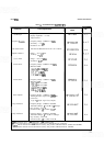
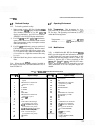
2-16.
When the HP
8559A is properly installed in
the display mainframe, the interconnections are as
listed in Table 2-2.
Pin on PI
1
2
3
4
5
6
7
8
9
10
11
12
13
14
15
16
2
-
18. Temperature.
This instrument has been
type tested for 95 percent relative humidity at
40°C
for five days. The operating environment should be
within the following limits:
....................
Temperature 0 to 55°C
.........
Altitude
<4572 meters (1 5,000 feet)
2
-
19. Modifications
2-20. A Modification Kit, HP Part Number 00180-
69503, provides materials and information necessary
to add Option 807 rear-panel connections to the
standard HP 180
-
series display. Refer to Table 1-3 in
Section
I.
Option 807 is factory-installed in HP
180TR, HP 181T, HP 181TR, and HP 182T main-
frames. The modification kit is required for use with
other mainframes if all four rear
-
panel outputs are
needed.
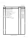
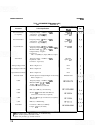
TABLE
2-2.
HP MODEL8559A MAINFRAME INTERCONNECTIONS
Signal or Voltage
CRT HORIZ (adjusted horizontal
signal)
GROUND from mainframe
(jumpered to pin 8)
NC
L NORM
Y
NORM
NC
SING SWP
GROUND from mainframe
(jumpered to pin
2)
MAN
SWP
NC
AUX
D
Horizontal Output
(to mainframe rear panel)
AUX C
21.4
MHz
IF Output
(to mainframe rear panel)
AUX B Penlift/Blanking Output
(to mainframe rear panel)
AUX A Vertical Output
(to mainframe rear panel)
GROUND
NC
Pin on PI
17
18
19
20
2
1
2 2
23
24
2 5
26
27
28
29
30
3
1
3 2
W5
(2
contacts)
Signal or Voltage
BLANKING
NC
GROUND from mainframe
(jumpered to pin
24)
AUTO SWP
BEAM
FINDER
NC
NC
GROUND from mainframe
Cjumpered to pin
19)
NC
NC
NC
-
1
2.6
VDC from mainframe
+
15
VDC from mainframe
+I00
VDC from mainframe
30V p
-
p from mainframe
(for LINE TRIGGER)
NC
+VERT (top contact,
yellow wire)
-
VERT
(bottom contact,
orange wire)