


SERVICE MODEL
8559A
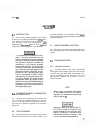
PROCEDURE:
Set HP
8559A
Spectrum Analyzer controls as follows:
TUNING
......................................................
.035 GHz
FREQ SPAN/DIV
.................................................
1 MHz
RESOLUTION BW
...............................................
300 kHz
INPUT
ATTEN
.....................................................
0 dB
REFERENCE LEVEL
...........................................
-
10 dBm
REFERENCE LEVEL FINE
.............................................
0
Amplitude Scale
........................................
10 dB/DIV
SWEEP TIME/DIV
...............................................
AUTO
SWEEP TRIGGER
............................................
FREE RUN
.....................................................
VIDEOFILTER OFF
BL CLIP
...........................................................
OFF
........................................................
SIGIDENT OFF
ALT IF
............................................................
OFF
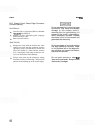
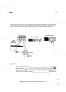
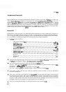
Connect equipment as shown. Set signal generator for a 35 MHz,
-
10 dBm output signal.
Center the Cal signal on the display and adjust for top graticule.
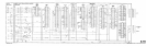
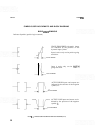
Using board extenders when necessary, check voltages and waveforms indicated on schematic
diagrams. Trigger oscilloscope on negative transition of AUX B
PENLIFT/BLANKING signal
from rear of display mainframe.
To measure RF power levels, set RESOLUTION BW control to
3
MHz and FREQ SPAN/DIV
to 0 (zero span). The first LO is not swept in zero span, allowing signal levels to be checked with
a second spectrum analyzer (use adapter cables
as
necessary). DO NOT use a power meter
(harmonics and LO signals will contribute to give erroneous levels).
FIGURE
8-2.
CONDITIONS FOR SCHEMATIC DIAGRAM MEASUREMENTS
(2
OF
2)