


MODEL 8559A
ADJUSTMENTS
ADJUSTMENTS
5
-
18. CALIBRATED SWEEP TIME ADJUSTMENT (Cont'd)
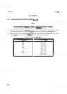
1. Set equipment controls as follows:
NOTE
If
an HP 853A Spectrum Analyzer Display mainframe is used, and a sweep
time faster than 10 msec is selected, an error message will appear on the
analyzer's CRT and the analyzer will go into mixed mode.
Spectrum Analyzer:
FREQUENCYBANDGHz
..................................................
.01-3
TUNING
............................................................
>0.010 GHz
FREQ SPAN/DIV
..........................................................
F (full)
RESOLUTION BW
...............................................
Optimum, coupled
INPUTATTEN
.............................................................
10dB
REFERENCE LEVEL
.......................................................
0 dBm
REFLEVELFINE
..............................................................
0
Amplitude Scale
........................................................
10 dB/DIV
SWEEP TIME/DIV
.........................................................
1 msec
SWEEP TRIGGER
.....................................................
FREE RUN
ALTIF
.....................................................................
OFF
SIGIDENT
.................................................................
OFF
BLCLIP
....................................................................
OFF
VIDEOFILTER
............................................................. OFF
50 MHz Universal Counter:
FUNCTION
............................................................
TI. A to B
SAMPLE RATE
...............................................
Full counterclockwise
TIMEBASE ................................................................ lops
SENSITIVITY(A)
........................................................
9o'clock
A
50 MHz INPUT
................................................
.v(falling edge)
SENSITIVITY(B) ........................................................ 9o'clock
B 10 MHz INPUT
.................................................
.n
(rising edge)
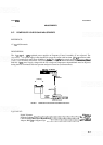
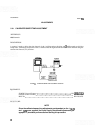
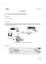
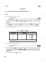
2. Connect equipment as shown in Figure
5
-
2.
3. Adjust counter SENSITIVITY controls (both channels) as necessary until counter triggers and indicates a
time interval of approximately 10.00 ms.
4.
Adjust 1 ms potentiometer A9R10 for a time interval indication of 10.00
+
0.80
ms.