


PERFORMANCE
TESTS
MODEL 8559A
PERFORMANCE TESTS
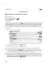
4.21.
BANDWIDTH SWITCHING (AMPLITUDE VARIATION)
SPECIFICATION:
Bandwidths 3 MHz to 300 kHz:
<
+
0.5 dB
Bandwidths 3
MHz to 1 kHz:
<
+
1
.O
dB
DESCRIPTION:
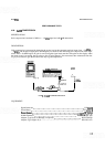
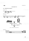
The CAL OUTPUT signal is applied to INPUT
50Q connector and displayed on CRT. The peak of displayed
35
-
MHz signal is centered on CRT and adjusted for a vertical deflection of several divisions. The amplitude
variation of the signal is measured for each RESOLUTION BW control setting. The overall variation between
RESOLUTION BW settings of 3 MHz through 300 kHz should be less than 1.0 dB
(k0.5 dB). The overall
variation between RESOLUTION BW settings of 3 MHz through 1 kHz should be less than 2.0 dB
(k
1.0 dB).
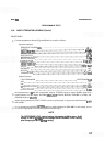
PROCEDURE:
Set spectrum analyzer controls as follows:
FREQUENCYBANDGHz
..................................................
.01-3
TUNING
.............................................................
0.035GHz
FREQSPAN/DIV
..........................................................
lMHz
RESOLUTION BW
...............................................
3 MHz, uncoupled
INPUT
AlTEN
.............................................................
10 dB
REFERENCE LEVEL
.......................................................
0 dBm
REFLEVELFINE
...........................................................
-
10
Amplitudescale
.........................................................
IdB/DIV
SWEEP TIME/DIV
........................................................
AUTO
SWEEPTRIGGER
.....................................................
FREERUN
ALTIF
.....................................................................
OFF
SIG IDENT
.................................................................
OFF
BLCLIP
....................................................................
OFF
VIDEOFILTER
.............................................................
OFF
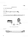
Connect CAL OUTPUT signal to INPUT
5(X2 connector.
Adjust TUNING control to center 35
-
MHz signal on CRT.
Adjust REF LEVEL FINE control to position peak of signal seven divisions above graticule baseline.
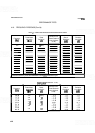
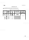
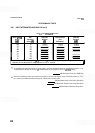
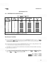
Set RESOLUTION BW and FREQ
SPAN/DIV controls to settings indicated in Table
4
-
8.
Record devia
-
tion of signal peak from reference graticule line for each RESOLUTION BW control setting. Values above
reference line set in step
4
are positive
(
+
);
values below reference line are negative
(
-
).
To find overall variation in Table
4-8,
algebraically subtract greatest negative amplitude deviation from
greatest positive amplitude deviation. If all changes in amplitude are of the same sign, overall variation is
largest positive or largest negative change in amplitude. Overall variation between 3 MHz and 300 kHz
RESOLUTION BW setting should be
<1.0 dB (k0.5 dB). Overall variation between 3 MHz and 1 kHz
RESOLUTION BW settings should be
<2.0 dB
(
+
1.0 dB).