


MODEL
8559A
SERVICE
Misapplied grease might cause intermittent switch connections. Utmost
care must be taken during reassembly to avoid excessive application of
grease and contamination of switch contacts. Avoid getting grease on
fingers.
ASSEMBLY OF FRONT SWITCH ASSEMBLY
1.
Assembly of Lock:
a. Lightly grease Locking Shaft
(3)
and insert into Front Switch Diecast
(1).
Lightly grease bearing
surfaces of Locking Link
(5).
b. Insert Lock Spring
(2)
into Front Switch Diecast
(1).
Press Locking Link
(5)
fully into Front Switch
Diecast and insert Dowel Pin
(4)
through access cutout (left side of lock boss) to hold lock mecha-
nism in place. Check for correct lock operation.
2.
Installation of Rotor Assemblies:
a.
Lightly grease all switch rotor detent holes on back of Front Switch
Diecast
(1).
b. Place Front Switch Assembly on flat working surface with front panel face
-
down and lock mecha-
nism facing you. Prop sides of switch assembly to provide clearance for knobs and shafts during
assembly (be careful not to scratch front panel enamel).
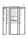
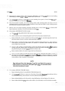
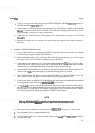
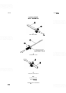
c. Inspect SWEEP TRIGGER rotor assembly
(10
-
12, 24
-
27).
Stop Arm
(26)
and Horseshoe Spring
(27)
are held in position by Push-on Retainer
(25)
and should move smoothly without binding (see
Figure
8-8A). Roll Pins
(12)
should be positioned in hole
7
and hole 18 on SWEEP TRIGGER Rotor
(24).
Check that Spring
(1 1)
and Ball Bearing
(10)
are in position.
d.
Lightly grease long side of SWEEP TRIGGER Shaft
(24)
and insert SWEEP TRIGGER rotor
assembly into left-most bushing in Front Switch
Diecast
(1).
Position rotor so that Ball Bearing
(10)
aligns
with
stop boss on left side of Front Switch Diecast.
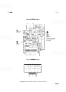
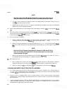
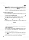
e. Inspect SWEEP TIME/DIV rotor assembly
(10,
11,
21, 22, 24),
Figure 8-8B. MANUAL SWEEP
Shaft
(22)
should be lightly greased and should turn freely inside SWEEP TIME/DIV Shaft
(24).
Check that Spring
(1 1)
and Ball Bearing
(10)
are in position. Note that there are no roll pins inserted
in the SWEEP
TIME/DIV Rotor
(24).
f. Lightly grease long side of SWEEP TIME/DIV Shaft
(24)
and insert SWEEP TIME/DIV rotor
assembly into next bushing in Front Switch
Diecast
(1).
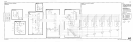
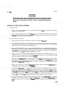
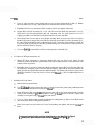
g.
Inspect FREQ
SPAN/DIV rotor assembly
(9
-
12, 14
-
17).
If Drive Hub
(15)
has been loosened or
removed from Frequency Span Shaft
(9),
refer to Figure 8-8C for correct dimensions for adjustment.
Roll Pins
(12)
should be positioned in hole
15
and hole
17
on Frequency Span Rotor
(14),
as shown in
Figure
8-8C. Slotted Bushing
(16),
Hairpin Spring
(17),
and Frequency Span Shaft must be lightly
greased where they contact each other for proper operation of push-pull mechanism. Check that
Springs
(1 I),
Ball Bearings
(lo),
Slotted Bushing, and Hairpin Spring are in correct position.
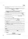
h.
Lightly grease long side of Frequency Span Shaft
(9)
and insert FREQ SPAN/DIV rotor assembly
(9
-
12, 14
-
17)
into next bushing in Front Switch Diecast
(1).
Position FREQ SPAN/DIV rotor
assembly so that stop boss on Front Switch
Diecast does not fall within small span between
Roll
Pins
(12).