


ADJUSTMENTS
ADJUSTMENTS
MODEL 8559A
5
-
27.
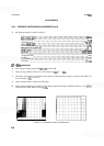
THIRD CONVERTER ADJUSTMENTS
REFERENCE:
A10 Schematic
DESCRIPTION:
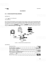
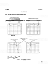
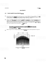
First, the Third LO is adjusted for proper frequency using a frequency counter. Next, the second IF
bandpass
filter is aligned by injecting
a
frequency modulated 321.4 MHz signal at the necessary level and monitoring the
21.4 MHz output signal with another spectrum analyzer. The filter is aligned for a
bandpass wide enough to
accommodate any frequency drift occurring in the RF section of the analyzer and the amplitude necessary to
provide the overall gain characteristics required by the analyzer.
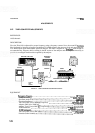
SPECTRUM ANALYZER
Dl SPLAY
ADAPl
EXTENDER
CABLE
ASSEMBLY
MICROWAVE
COUNTER
FUNCTION
QENERATOR
OUTPUT
'ER ADAPTER
6
SWEEP R F
I
OSCILLATOR PLUG
-
IN
I
.
.
SPECTRUM
ANALYZER
ADAPTER
OUTPUT
ADAPTER ATTENUATORS
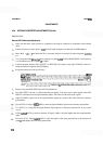
FIGURE 5
-
14. THIRD CONVERTER ADJUSTMENTS TESTSETUP
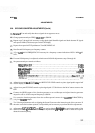
EQUIPMENT
FrequencyCounter
.......................................................
HP5342A
Sweep Oscillator
..................................................
HP 8620(3/86222A
Spectrum Analyzer
.......................................................
HP 8569B
Function Generator
......................................................
HP 33 10A
Test Cable, BNC (m) to SMB
(f)
(2 required)
.............................
HP85680-60093
Adapter, SMC (m) to SMC (m)
..........................................
HP 1250
-
0827
Adapter, Type N
(m)
to BNC
(f)
(3 required)
...............................
HP 1250
-
0780
20 dB Attenuator
..............................................
HP 8491B, Option 020
10dBAttenuator
..............................................
HP8491B,Option010
Test Cable, BNC (m) to SMC
(f)
.......................................
HP
1
l592-60001
Extender Cable Assembly
..............................................
HP 5060
-
0303