


SERVICE
MODEL
8559A
8. Installation of Knobs:
a. Turn SWEEP TRIGGER Shaft (24) fully clockwise (as seen from front of Front Switch Assembly) to
spring
-
loaded SINGLE position and release. Use a no. 4 hex wrench to install SWEEP TRIGGER
knob with SINGLE line aligned with painted arrow on front panel. Check for proper switch opera
-
tion and alignment.
b. Turn SWEEP
TIME/DIV Shaft (24) to align Ball Bearing (10) on SWEEP TIME/DIV Rotor with
left
-
most edge of stop boss on Front Switch Diecast (1). This positions SWEEP TIME/DIV Rotor
with Ball Bearing slightly right of 12 o'clock position (as seen from front of Front Panel Assembly).
Use a no. 4 hex wrench to lightly tighten SWEEP
TIME/DIV knob onto SWEEP TIME/DIV Shaft
with approximately center of green AUTO position aligned with painted arrow on front panel. Turn
SWEEP
TIME/DIV knob to any calibrated sweep time position and align knob markings exactly
with painted arrow on front panel. Tighten SWEEP
TIME/DIV knob and check for proper switch
operation and alignment.
c.
Uncouple RESOLUTION BW Shaft (55) from FREQ
SPAWDIV Shaft
(9)
by pulling both shafts
out. Turn each shaft fully clockwise. Use a no. 6 hex wrench to install FREQ
SPAN/DIV knob with
100 MHz indicated, checking that the plastic indicator guide on back of knob does not completely
bottom into hole in Front Switch
Diecast
(1).
Use a no. 4 hex wrench to install RESOLUTION BW
Knob with 3 MHz indicated. Check for proper operation and alignment of both switches. Push
-
pull
action should be smooth and positive.
d.
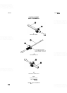
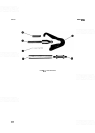
Set nylon shim
washer(s) and Index Disc (see Figure 6
-
1) in place on REFERENCE LEVEL knob to
check for proper shim width. Nylon washers should shim Index Disc slightly away from labelled ring
on REFERENCE LEVEL knob to prevent rubbing against painted numbers. Add or remove shim
washers as necessary to provide slight clearance.
e.
Turn Attenuator Drive Rotor (8) fully counter
-
clockwise so that Input Attenuator Pointer guide pin
(P/O
8)
is at bottom of front panel. Turn Ref Level Shaft
(6)
fully clockwise. Place plastic Input
Attenuator Pointer over guide pin (pointer should indicate 70 dB). Place large end of conical spring
against Input Attenuator Pointer and slide REFERENCE LEVEL knob, nylon
washer(s), and Index
Disc (from step d) onto Ref Level Shaft, securing with retainer clip.
f. Use a no. 6 hex wrench to adjust Miter Gears (51) for alignment of Input Attenuator Pointer with 70
dB front panel label and proper gear mesh (Input Attenuator A3 still in full counter
-
clockwise posi
-
tion).
g.
Turn REFERENCE LEVEL knob to indicate level of
-
30 dBm signal and tighten knob securely
with a no. 6 hex wrench. Check for proper operation and alignment of REFERENCE LEVEL and
INPUT
ATTEN controls, and readjust knob, gears, and Rotating Lockout (70) as necessary. Refer
-
ence Level should range from
-
10 dBm to
-
100 dBm with 0 dB INPUT ATTEN selected.
h. Turn REF LEVEL FINE Shaft (65) fully counter
-
clockwise and use a no. 4 hex wrench to install REF
LEVEL FINE knob with
0 dB indicated. Check for proper operation and alignment and readjust
knob as necessary.
i.
Turn BASELINE CLIPPER Shaft and VIDEO FILTER Shaft (33) fully counter
-
clockwise and use a
no. 2 spline wrench to
install BASELINE CLIPPER and VIDEO FILTER knobs in OFF position.
Check for proper operation and alignment and readjust as necessary.
j.
Install flat and wavy washers on coarse tune shaft as indicated in Figure 6
-
1. Compress these washers
with retaining ring. A torque of about
1
in
-
oz should be required to turn coarse tune shaft.
k. Use a no.
4
hex wrench to install COARSE TUNE and FINE TUNE knobs. Base of COARSE TUNE
knob should clear front panel. Check for proper operation of TUNING control.